Installing an Optional Ethernet Expansion Module
Hardware Installation 3-3
3.4 INSTALLING AN OPTIONAL ETHERNET EXPANSION MODULE
Installing an Ethernet expansion module involves the following:
• Removing the front panel coverplate (Section 3.4.1)
• Installing the Ethernet expansion module (Section 3.4.2)
3.4.1 Removing the Front Panel Coverplate
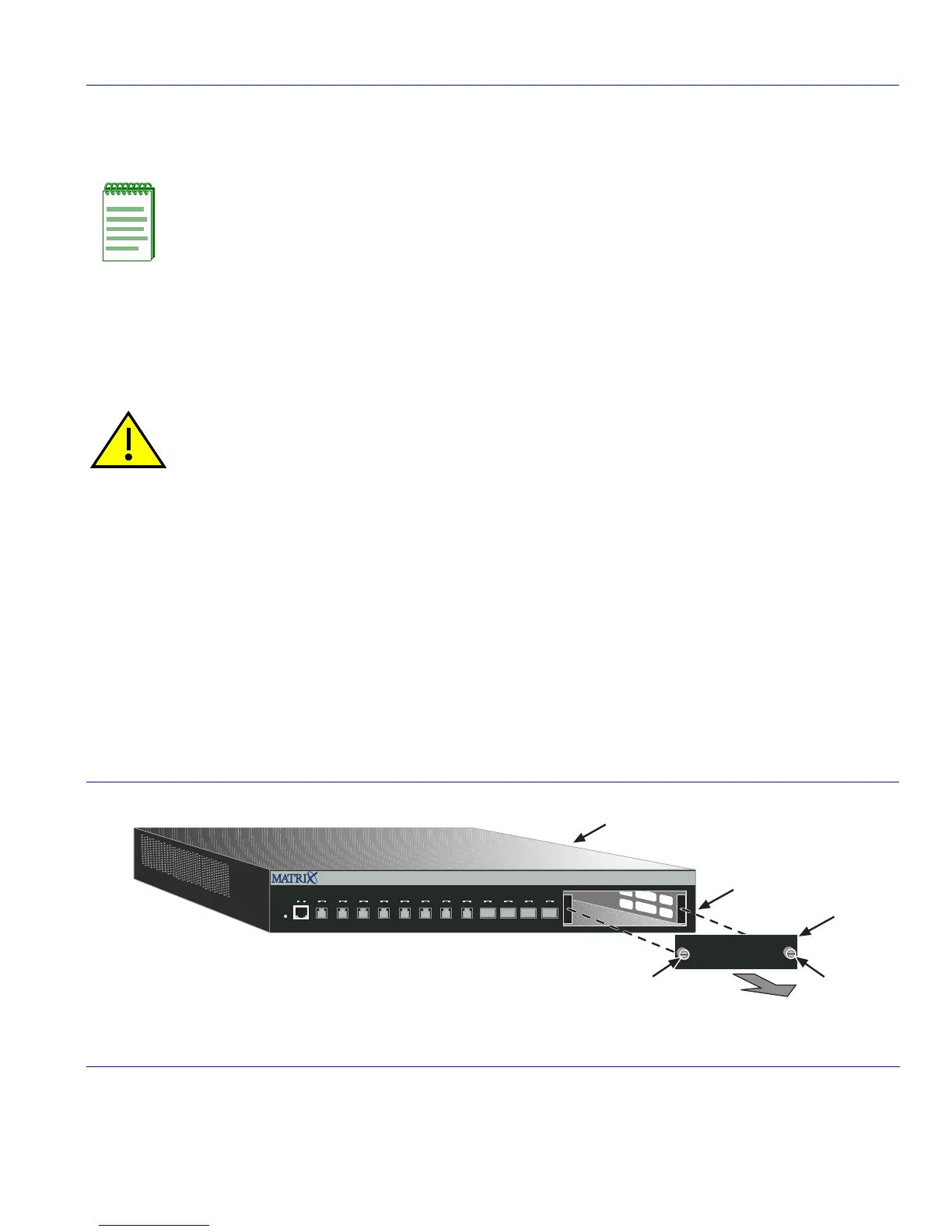
Refer to Figure 3-1 and proceed as follows:
1. Attach the antistatic wrist strap (refer to the instructions on the antistatic wrist strap package).
2. Place the 1G694-13
➀ on an antistatic pad (not shown) on a sturdy flat surface.
3. Loosen the two captive screws
➁ until the coverplate ➂ is released from the front panel ➃.
4. Remove the coverplate
➂ from the front panel ➃. Save the coverplate for future use if necessary.
Figure 3-1 Removing the Front Panel Coverplate
Note: Install any optional equipment before proceeding to Section 3.7.
Caution: An antistatic wrist strap is required to perform the following procedures to minimize ESD
damage to the devices involved.
Precaución: Para minimizar los efectos de las descargas de electricidad estática, deberá utilizar
una pulsera antiestática al realizar los siguiente procedimientos.
➀
1G694-13
➂
Coverplate
➁
Coverplate captive screws (2)
➃
Front panel
1G694-13
2345678
9101112
Reset
Console
CPUPWR
1
À
Á
Á
Ã
Â
 Loading...


