Connecting to Console Port for Local Management
Hardware Installation 3-19
3.10.2 Connecting to an IBM or Compatible Device
To connect an IBM PC or compatible device, running the VT terminal emulation, to an
Enterasys Networks module Console port (Figure 3-11), proceed as follows:
1. Connect the RJ45 connector at one end of the cable (not supplied) to the Console port on the
Enterasys Networks module.
2. Plug the RJ45 connector at the other end of the cable into the RJ45-to-DB9 adapter (supplied
with the switch).
3. Connect the RJ45-to-DB9 adapter to the communications port on the PC.
4. Turn on the PC and configure your VT emulation package with the following parameters:
5. When these parameters are set, the Local Management password screen will appear. Refer to the
appropriate Matrix E1 1G694-13 Configuration Guide for further information.
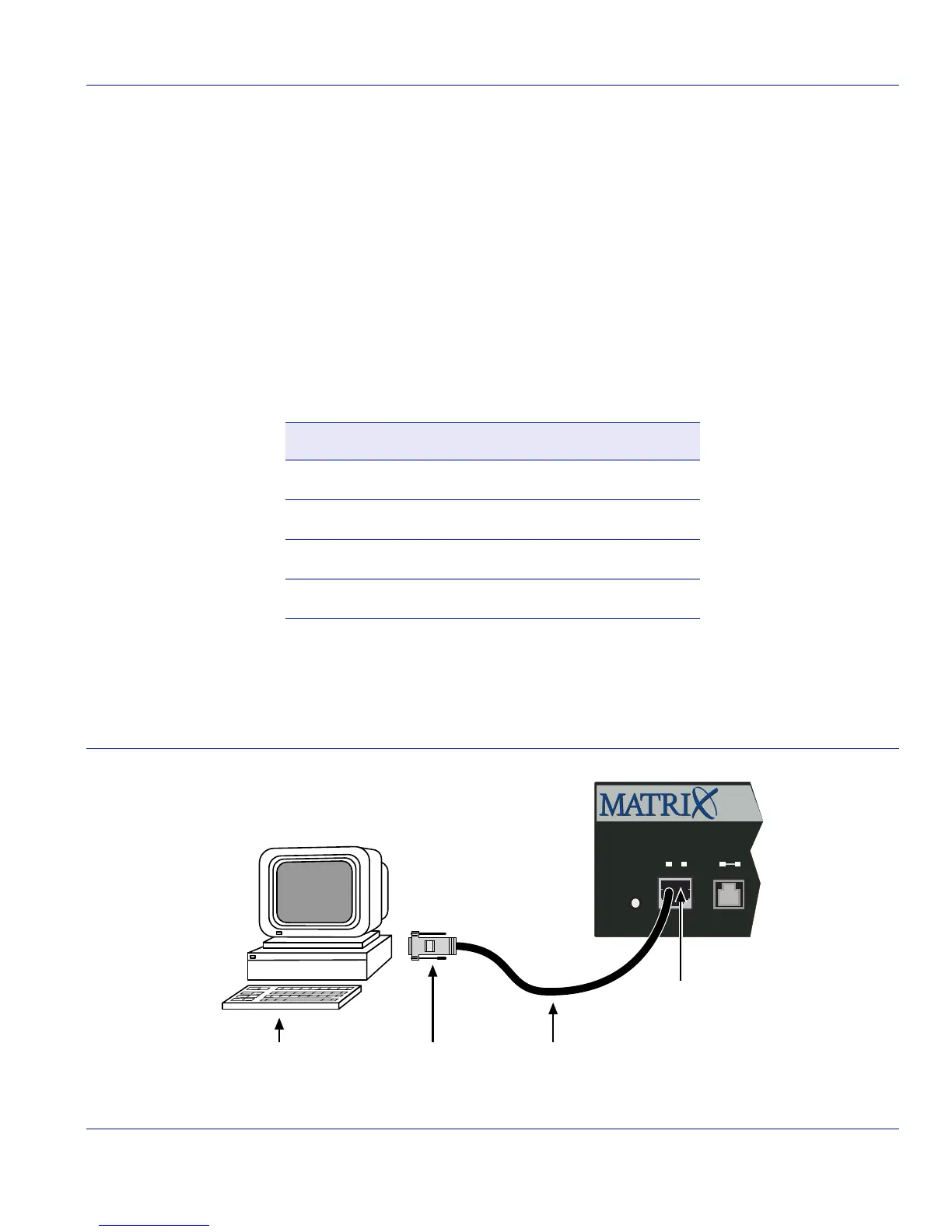
Figure 3-11 Connecting an IBM PC or Compatible
Parameter Setting
Mode 7 Bit Control
Transmit Transmit=9600
Bits Parity 8 Bits, No Parity
Stop Bit 1 Stop Bit
➀
UTP cable with RJ45 connector
➂
RJ45-to-DB9 PC adapter
➁
RJ45 console port
➃
PC
1
Reset
Console
CPUPWR
1G694-13
Á
ÂÃ À