Using LANVIEW
4-2 Troubleshooting
4.1 USING LANVIEW
The 1G694-13 switch uses the Enterasys Networks built-in visual diagnostic and status monitoring
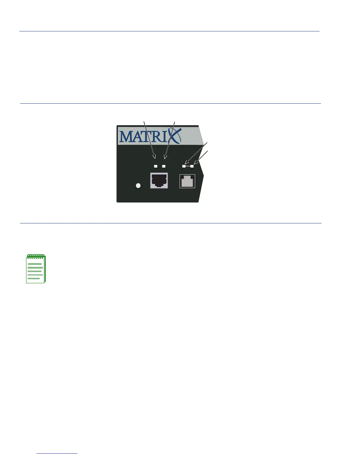
system called LANVIEW. The LANVIEW LEDs (Figure 4-1) allow you to quickly observe
network status for diagnosing network problems.
Figure 4-1 LANVIEW LEDs
Table 4-1 describes the LED indications and the associated recommended actions.
➀
PWR LED
➂
Port RX LED
➁
CPU LED
➃
Port TX LED
NOTE: The terms flashing, blinking, and solid used in Tabl e 4 - 1 indicate the following:
Flashing: LED is flashing randomly.
Blinking: LED is flashing at a steady rate (approximately 50% on, 50% off).
Solid: LED is on steady and not pulsing.
1
Reset
Console
CPUPWR
1G694-13
Á
Ã
À
Â
 Loading...


