Setting the Mode Switches
B-4 Mode Switch Bank Settings
B.3 SETTING THE MODE SWITCHES
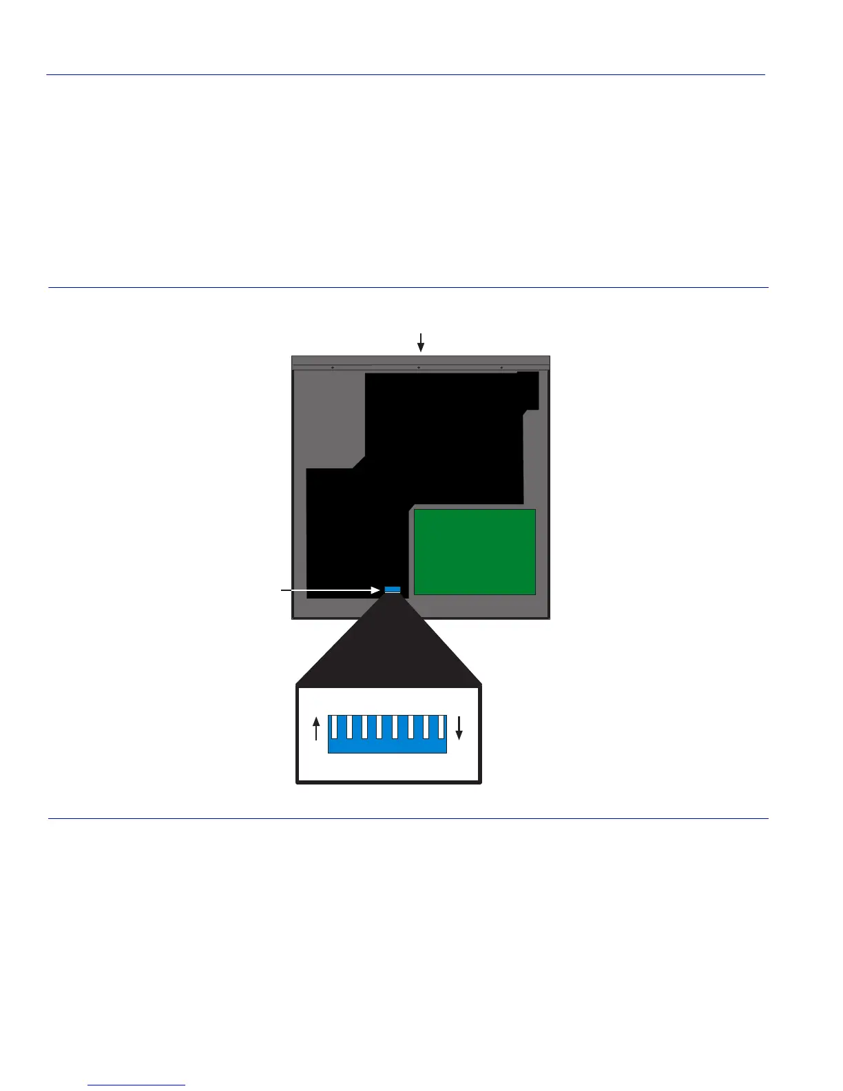
Figure B-2 shows the location of the mode switches and the switch settings for normal operation.
These switches are set at the factory and rarely need to be changed.
Switch definitions and positions are as follows:
• Switches 1 through 5 – Reserved for future use.
Figure B-2 Mode Switch Location (Chassis, Top View)
• Switch 6 – Force Download. Changing the position of this switch initiates an Xmodem
download of the functional image via the console port on the next power-up of the device. You
must connect the console port to a terminal emulator that supports the Xmodem protocol (such
as HyperTerminal).
➀
Front panel
➁
Mode switch bank
Power Supply
À
MODE SWITCH BANK
OFFON
12345678
Á