2.1.2 Power Supply Circuit
This printer can be powered between three power supply boards: the
C166PSB(120V), C166PSE(220-240V) and C244PSH(120V/220-240V).
The function of these boards s the same, except for a different in a primary
circuit. The input voltages and fuse ratings for these boards are shown
below;
Table 2-1. Power Supply Board
Board Input Voltage Fuse F1 Rating
C166PSB 103.5 - 132V 3.15A / 125V
C166PSE 198 - 264V T2.0AH / 250V
C244PSH 85 - 138V / 187 - 276V 5HT4
2.1.2.1 Power Supply Overview
The power supply board has two DC power outputs for control circuit and
printer mechanism. These power outputs are listed on following table;
Table 2-2. Power Supply Outputs Applications
Output Voltage Applications
+5VDC
• Control Circuit board Logic
• Detectors
• Operation Panel LEDs
+35VDC
• CR Motor
• PF Motor
• Printhead
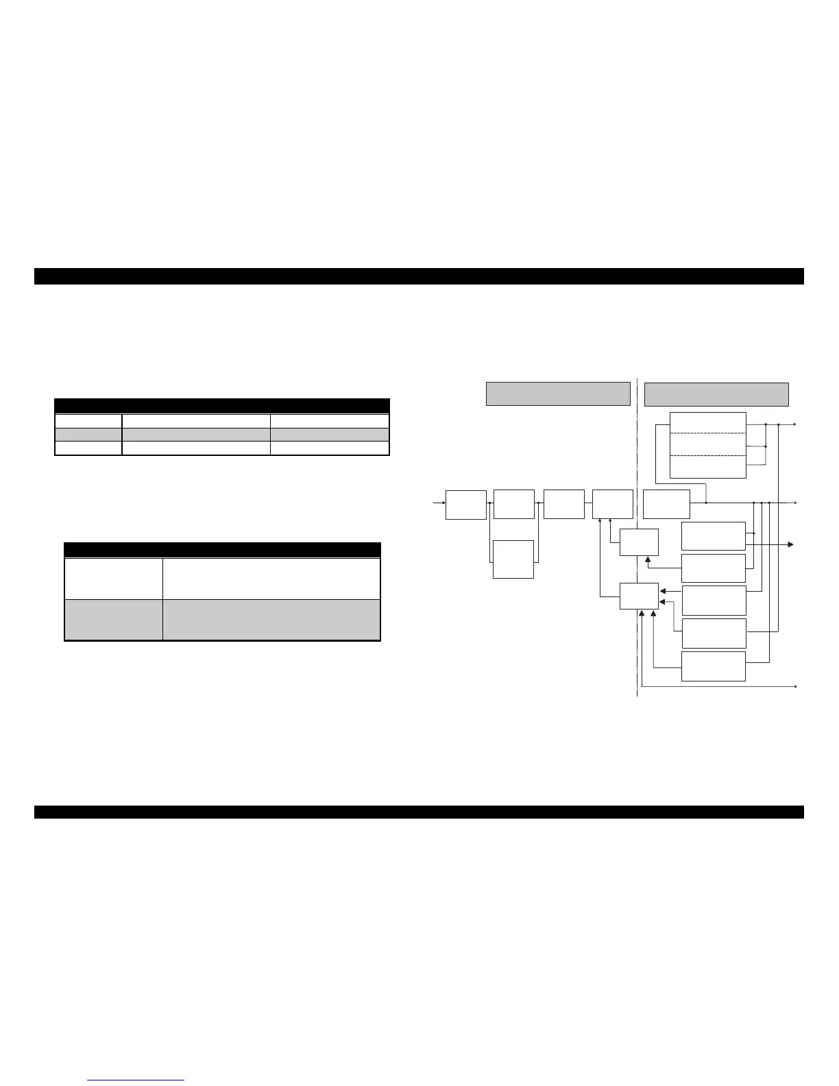
The block diagram of power supply circuit is shown following figure. When
AC power enters the printer from external power source, the filter circuit
removes the noise. Then AC voltage undergoes full-wave rectification and
smoothed to produce direct voltage. But, in case of C244PSH board, the AC
voltages undergoes the voltage doubler rectification automatic switching IC
and smoothed to produce direct voltage. The voltage is fed to the gate port
for the switching FET (Q1)through resistors (R18 and R31), and then the
switching circuit operates.
The secondary smoothing circuit produces a stepped down +35VDC
voltage. The +5VDC is generated and stabled by feeding the +35VDC
voltage through the +5VDC power supply circuit IC. As this power supply
circuit composed of an ZC-RCC (zero cross ringing choke converter), it
realizes to the circuit high stability, efficiency and portability.
This circuit provides the power switch (operate switch) in the secondary
circuit system. The operate switch on the operation panel controls the power
supply circuit.
There is +35v line constant voltage control circuit and over current / voltage
circuits in order to protect the printer and control circuit.
Filter C ircuit
F u ll W a v e
R e c tific a tio n
Circuit
Sm oothing
Circuit
Switching
Circuit
AC input
Sm oothing
Circuit
+5V Switching
Regulator
+5V O ver current
Protection C ircuit
+35V D C
+5V D C
Photo-
Coupler
Photo-
Coupler
+35V Line
Over Voltage
Protection C ircuit
+35V Line
O ver Load
D etector C ircuit
+35V Line
O ver C urrent
Protection C ircuit
O peration
S W
Secondary C ircuit
CPU
Port 20
+35V Line
C onstant V oltage
Control Circuit
+5V Line
O ver V oltage
Protection C ircuit
+5V C onstant Voltage
Control Circuit
V oltage
Doubler
R e c tific a tio n
A u to -s w itc h in g
Circuit
C244PSH only
Prim ary C ircuit
Figure 2-2. Power Supply Circuit Block Diagram

 Loading...


