4.2.10 Disassembly and Assembly of CSF Bin 1
This section describes procedure for disassembling and assembling the
operational cut sheet feeder. In general, you can install a component in the
CSF simply by reversing the procedure for removing. Therefore, this section
dose not describe assembly procedures in most cases. If necessary, special
notes on assembling a component are given at the end of description of
each procedure.
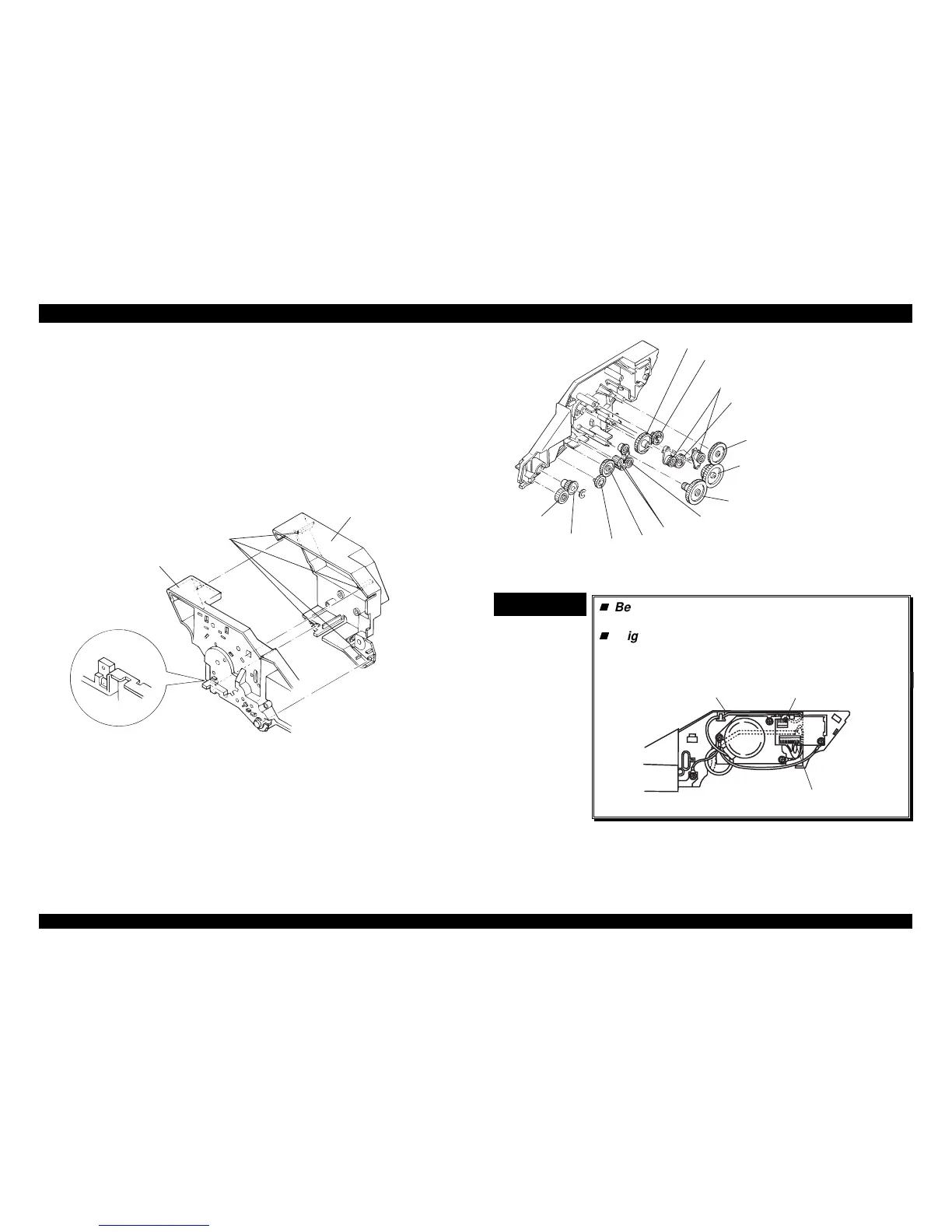
4.2.10.1 Disassembling the Right Side Block
1. Remove the CFS gear cover by pushing and releasing the 4 clips in the
following figure.
CSF Gear Cover
R ight C S F Fram e
C lip s
Figure 4-37. Releasing the clips for the CSF Gear Cover
2. Remove three CPB tight (3 × 12) screws securing the stepping motor to
the CSF frame.
3. Disconnect connector CN1 from the CSF board assembly, ans then
remove the stepping motor.
4. Remove one CPB tight (3 × 12) screw securing the CSF board
assembly, and disconnect connector CN2.
5. Remove the CSF board assembly by releasing one clip fixing the CSF
board assembly to the right CSF frame.
6. Remove the 13 gears mounted on the right CSF frame.
G ear 18
G ear 15
G ear 15.5
G ear 10
Paper Eject Transm ission G ear A
C S F Planetary Lever S ub Assem bly
G ear 29
D riven Transm ission G ear
Paper Eject D riven Transm ission G ear
C S F Planetary Lever A ssem bly
G ear 30
C om bination G ear 20/33.5
C om bination G ear 8.5/33
Figure 4-38. Engaging 13 Gears
CHECK POINT
9
Be careful of the cable alignment for the CN1
connector cable and earth cable.
Align those cables as shown in the following
figure. If these cables are not aligned properly,
the CSF gear cover cannot be assembled
properly.
R ight C S F Fram e
CN1
CN2
Figure 4-39. Cable Alignment

 Loading...


