4.2.9.11 Removing the Main Board Assembly
1. Remove the printer cover, the rear / front edge guide assemblies, front
cover, paper eject assembly, and rear / fronts tractor units. (Refer to
Section 4.2.1.)
2. Remove the panel board assembly. (Refer to Section 4.2.2.)
3. Remove the upper housing assembly. (Refer to Section 4.2.7.)
4. Disconnect the following connectors from the main board assembly.
Table 4-8. Connectors’ List
Number Pin Connector
Color
Number Pin Connector
Color
CN3 10 white CN4 3 white
CN5 3 black CN6 2 white
CN7 4 gray CN8 18 gray
CN9 16 gray CN10 4 white
CN11 5 white CN12 4 white
CN13 4 black CN15 22 white
Note1 :Disconnect the cable for CN10 and CN11 after releasing the
connector locks by pulling up.
Note2 : Disconnect the cable for CN3 by pushing down the connector cover.
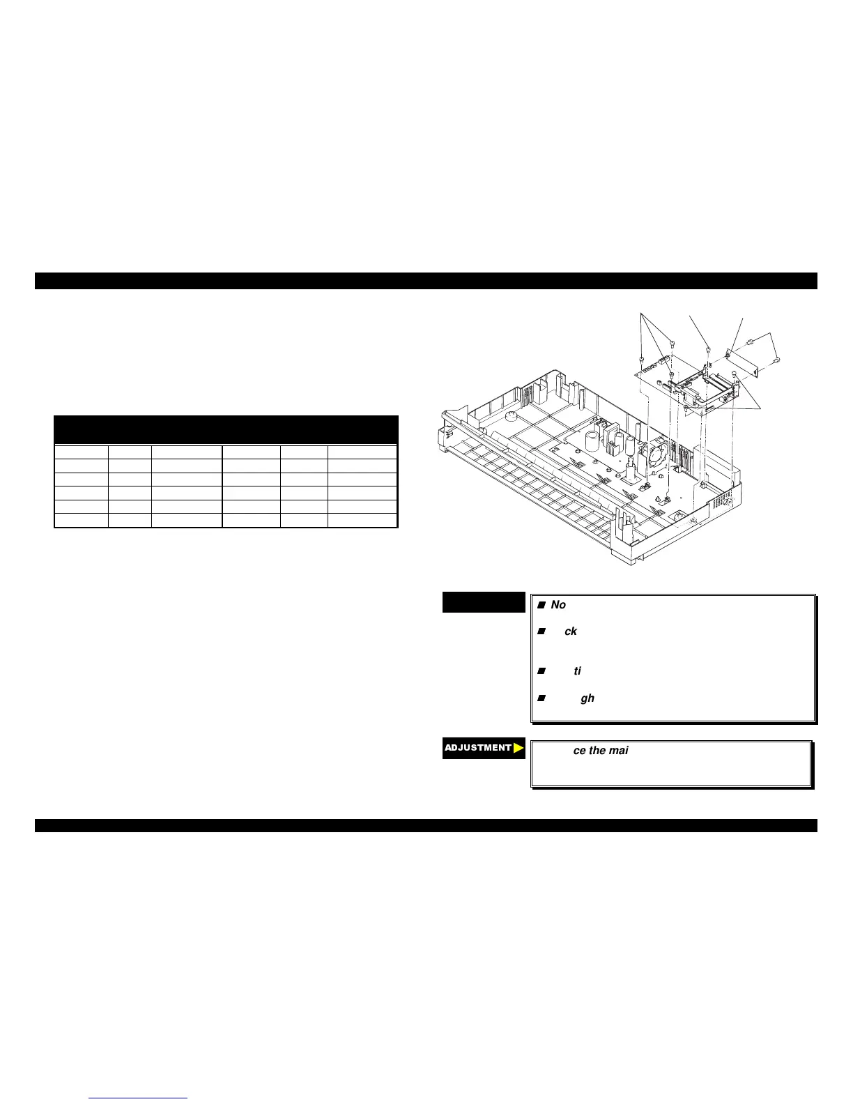
5. Remove three CBS screws (3 × 4) securing the upper shield plate to
the printer mechanism and the upper I/F grounding plate on the main
board assembly.
6. Remove two CBS screws (3 × 12) securing the upper connector cover.
7. Remove five CBS screws (3 × 12) and one CBC lamitite screw (3 × 8)
securing the main board assembly to the lower housing assembly.
8. Remove the option I/F cage from the main board by releasing the hooks
which is fixing it to the main board.
9. Remove the main board assembly with the upper I/F grounding plate.
CBS(3x12)
CBB(3x12)
CBC(3x8)
CBB(3x12)
U pper C onnector C over
Figure 4-35. Removing the Main Board Assembly
CHECK POINT
9
Notice the location of CBC lamitite screw (3 ×× 8)
refer to the following figure.
Lock CN10 and CN11 by pushing down each
connector’s lock after inserting the connector
cable.
The tightening torque for the CBB screws (3 ××
12) : 0.78 ∼∼ 0.98 Nm (8 ∼∼ 10 Kgf-cm)
The tightening torque for the CBB screws (3 ×× 8)
: 0.78 ∼∼ 0.98 Nm (8 ∼∼ 10 Kgf-cm)
$'-8670(17
If replace the main board, adjust the bi-directional
print alignment and run the default setting
program. (Refer to Chapter 5.)

 Loading...


