4.2.9.4 Removing the Right Frame Assembly
1. Remove the printer cover, the rear / front edge guide assemblies, front
cover, paper eject assembly, and rear / fronts tractor units. (Refer to
Section 4.2.1.)
2. Remove the panel board assembly. (Refer to Section 4.2.2.)
3. Remove the upper housing assembly. (Refer to Section 4.2.7.)
4. Remove the printer mechanism. (Refer to Section 4.2.9.)
5. Remove the CR motor assembly. (Refer to Section 4.2.9.1.)
6. Remove the PF motor. (Refer to Section 4.2.9.2.)
7. Remove the PG sensor assembly. (Refer to Section 4.2.9.3.)
8. Remove the hexagon nut (M4) securing the gap adjust lever. Then,
remove the lever from the right frame assembly.
9. Remove one CBS screws (3 × 6) securing the platen cover to the right
frame assembly.
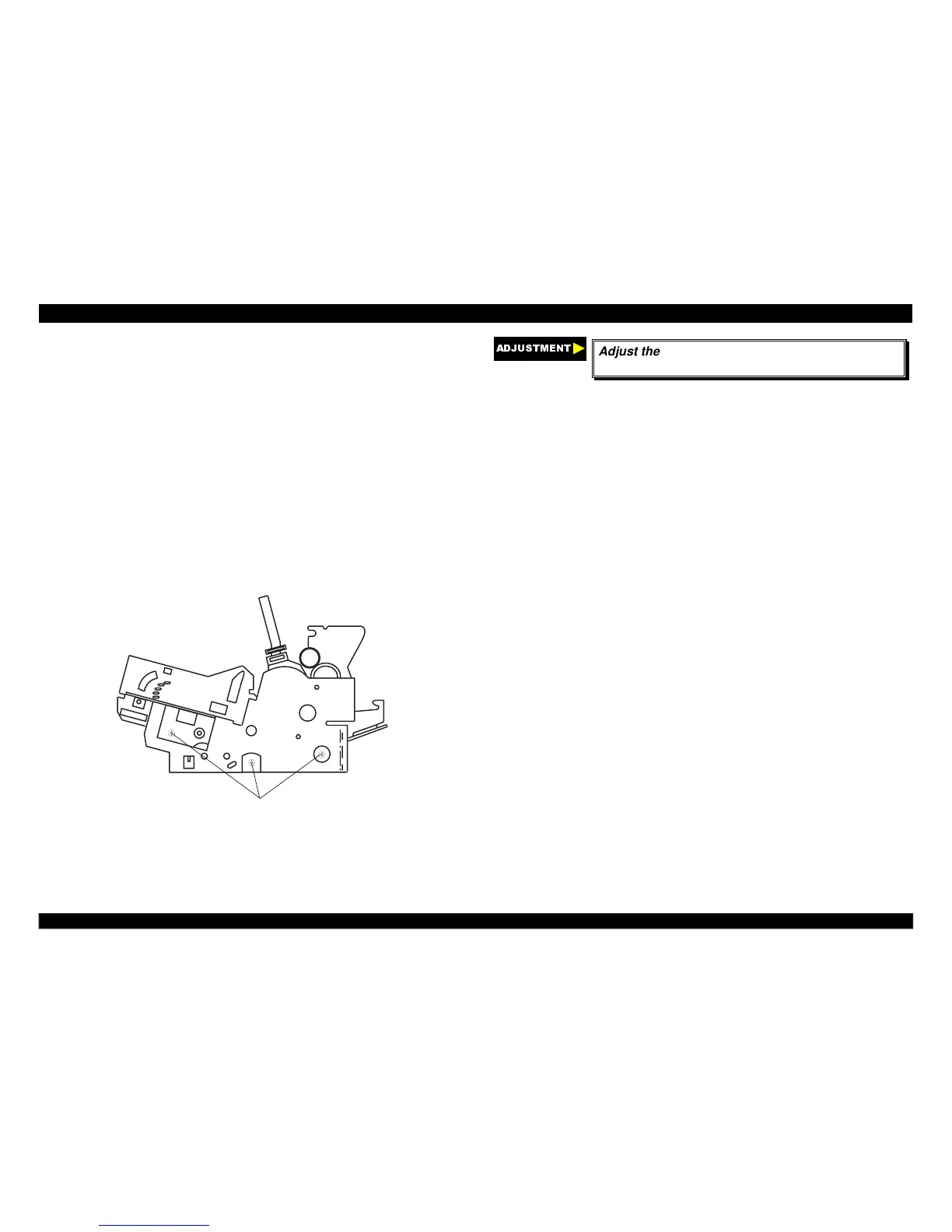
10. Remove two CBS screws (3 × 6) securing the right frame assembly at
the positions illustrated.
11. Remove the right frame assembly.
C B S S c re w (3 x 6 )
Figure 4-20. Removing the Right Frame Assembly
$'-8670(17
Adjust the platen gap and Bi-directional print
alignment. (Refer to Chapter 5.)
 Loading...


