4.2.9.6 Removing the Left Frame Assembly
1. Remove the printer cover, the rear / front edge guide assemblies, front
cover, paper eject assembly, and rear / fronts tractor units. (Refer to
Section 4.2.1.)
2. Remove the panel board assembly. (Refer to Section 4.2.2.)
3. Remove the upper housing assembly. (Refer to Section 4.2.7.)
4. Remove the printer mechanism. (Refer to Section 4.2.9.)
5. Disconnect two connector cables from two release lever sensors, and
then disconnect the connector cable from the HP sensor.
6. Remove the platen assembly. (Refer to Section 4.2.6.)
7. Remove one CBS screws (3 × 6) securing the platen cover to the left
and right frame assemblies.
8. Remove one hexagon nut (M4) securing the CR guide shaft and left
frame.
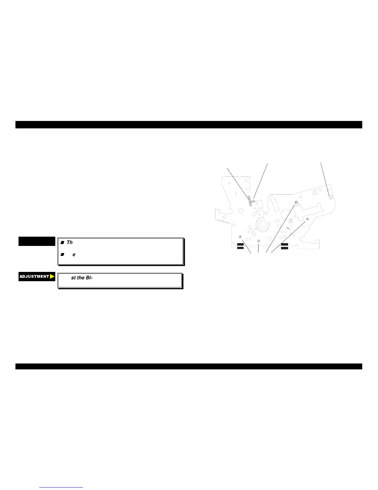
9. Remove four CBS screws (3 × 6) securing the left frame assembly.
10. Remove the left frame assembly.
CHECK POINT
9
The tightening torque for the CBS screws (3 ×× 6)
: 0.78 ∼∼ 0.98 Nm (8 ∼∼ 10 Kgf-cm)
The tightening torque for the hexagon nut : 1.18
∼∼ 1.37 Nm (12 ∼∼ 14 Kgf-cm)
$'-8670(17
Adjust the Bi-directional print alignment. (Refer to
chapter 4.)
C B S Screw (3 X 6 FZ/n ) S ecuring the Left Fram e Assem bly
H exagon N ut (N orm al, M 4)
Platen C over
C.B.S Screw (3 X 6 FZ/n)
Figure 4-25. Removing the Left Frame Assembly

 Loading...


