4.2.9 Removing the Printer Mechanism
1. Remove the printer cover, the rear / front edge guide assemblies, front
cover, paper eject assembly, and rear tractor unit. (Refer to Section
4.2.1.)
2. Remove the panel board assembly. (Refer to Section 4.2.2.)
3. Remove the upper housing assembly. (Refer to Section 4.2.7.)
4. Remove three CBS screws (3 × 4) securing the upper shield plate to
the printer mechanism and the upper I/F grounding plate on the main
board assembly.
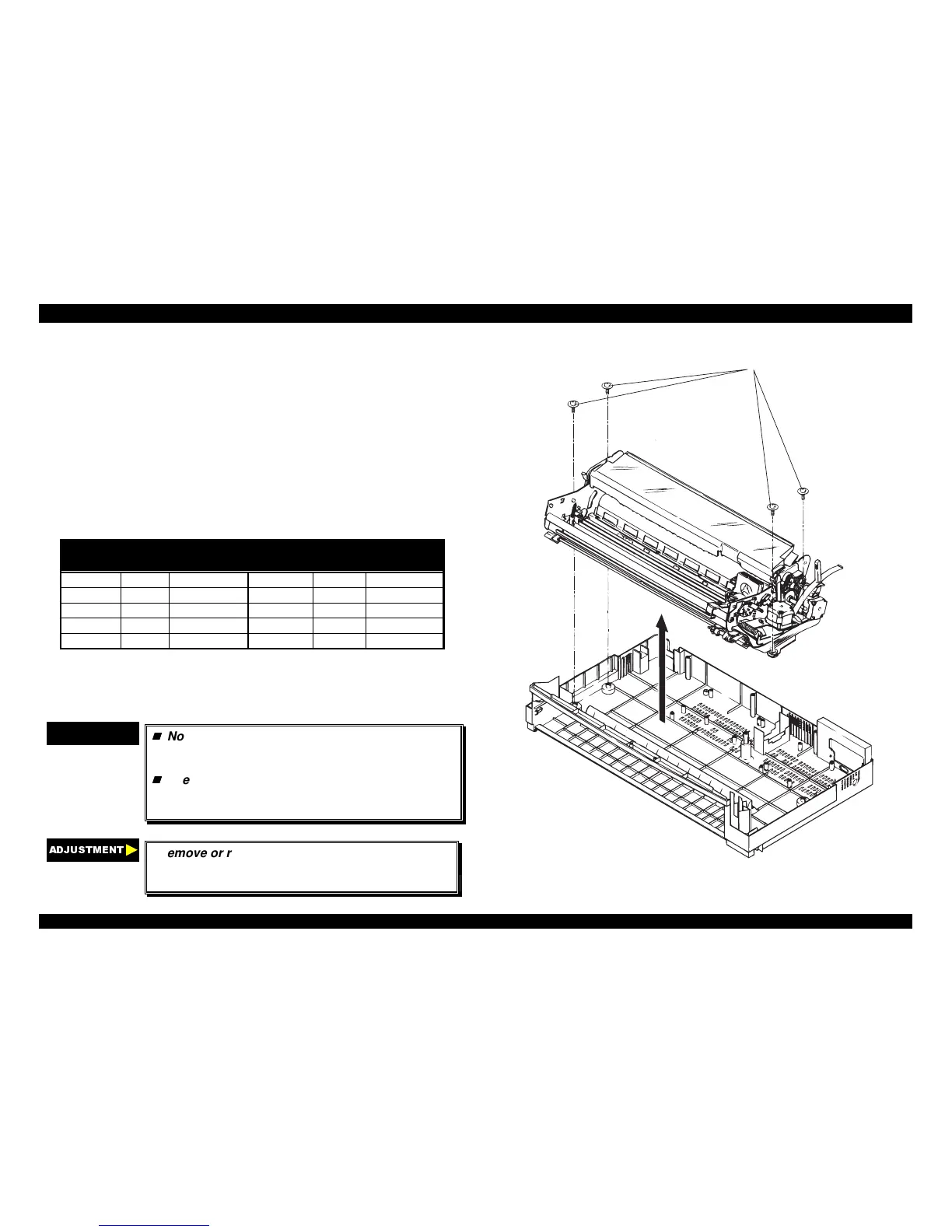
5. Remove four printer mechanism mounting screws securing the printer
mechanism.
6. Disconnect the following connectors on the main board assembly.
Table 4-7. Connectors’ List
Number Pin Connector
Color
Number Pin Connector
Color
CN4 3 white CN5 3 black
CN6 2 white CN7 4 gray
CN8 18 gray CN9 16 gray
CN10 4 white CN11 5 white
CN12 4 white CN13 4 black
Note : Disconnect the cable for CN10 and CN11 after releasing the
connector locks by pulling up.
7. Remove the printer mechanism.
CHECK POINT
9
Notice the connector for cables CN10 and CN11,
and align the red colored cable to pin 1 of the
connector.
The tightening torque for the printer mechanism
mounting screws : 0.78 ∼∼ 0.98 Nm (10 ∼∼ 12 Kgf-
cm)
$'-8670(17
If remove or replace the printer mechanism once,
adjust the bi-directional print alignment and reset
the TPE level. (Refer to Section Chapter4.)
Pritner M echanism M ounting S crew s
Figure 4-15. Removing the Printer Mechanism
 Loading...


