3.5 REPAIRING C244 MAIN BOARD ASSEMBLY
This section provides instructions for repairing C244 MAIN board
assembly. It describes various problem, symptoms, likely cases and
solutions. The check points columns provide proper waveforms, resistance
values and other information for each component of C244 MAIN.
CAUTION
This information is necessary only for servicers
who repair to the component level. Servicers who
repair to the unit level (including all servicers in
the U.S.) can ignore this section.
Table 3-10. Repairing C244 MAIN Board Assembly
Problem Cause Checkpoint Solution
The
printer
dose not
operate
at all.
Reset
IC15 is
defective.
Check the voltage waveforms
of the VCC signal (CH1 : IC15
pin 7) and /RESET signal (CH2
: IC15 pin 5) when the printer is
turned on.
CH 1
CH 2
Figure 3-12. Waveform 5
Replace the
main board or
IC15.
Table 3-11. Repairing C244 MAIN Board Assembly (Continued.)
Problem Cause Checkpoint Solution
The
printer
dose not
operate
at all.
The
PROM
(IC5) is
not
selected.
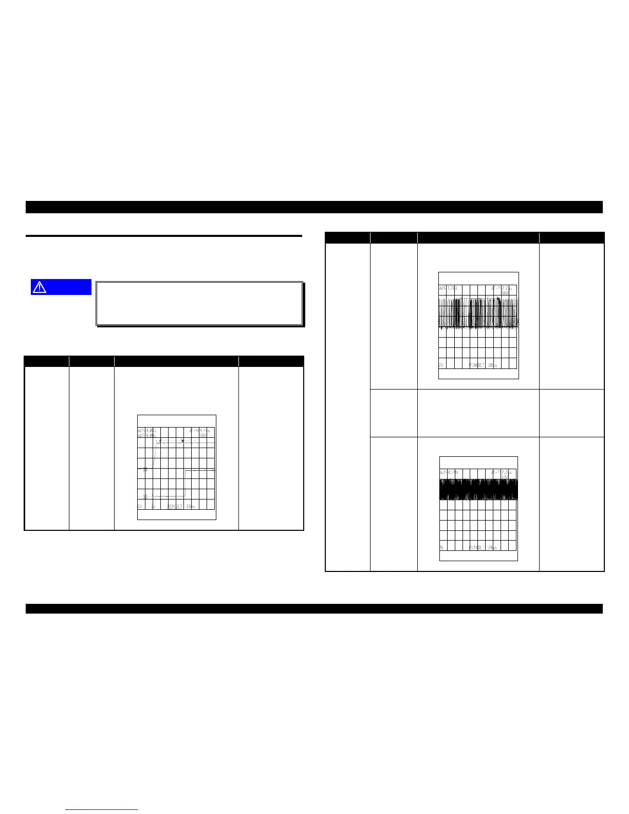
Check the signal for a change
in HIGH and LOW at pin 137
of IC1.
Figure 3-13. Waveform 6
Replace the
main board.
The
PSRAM
(IC3) is
not
selected.
Check the signal for a change
in HIGH and LOW at pin 132
of IC1.
Replace the
main board.
CPU (IC2)
is
defective.
Check the oscillator signal at
pins 26 or 27 of the CPU
Figure 3-14. Waveform 6
Replace the
main board.

 Loading...


