2.1.3 Control Circuit
The control circuit consists of C244MAIN control board and the operation
panel board.
2.1.3.1 Overview of Control Circuit Operation
This printer’s control circuit includes a TMP96C141BF that ran at 17.20MHz,
an E05B50** gate array, a 2Mbit PROM (or 2M / 4Mbit Flash-ROM), a 1Mbit
/ 4Mbit PS-RAM (or SRAM), a serial EEPROM (or parallel EEPROM) and
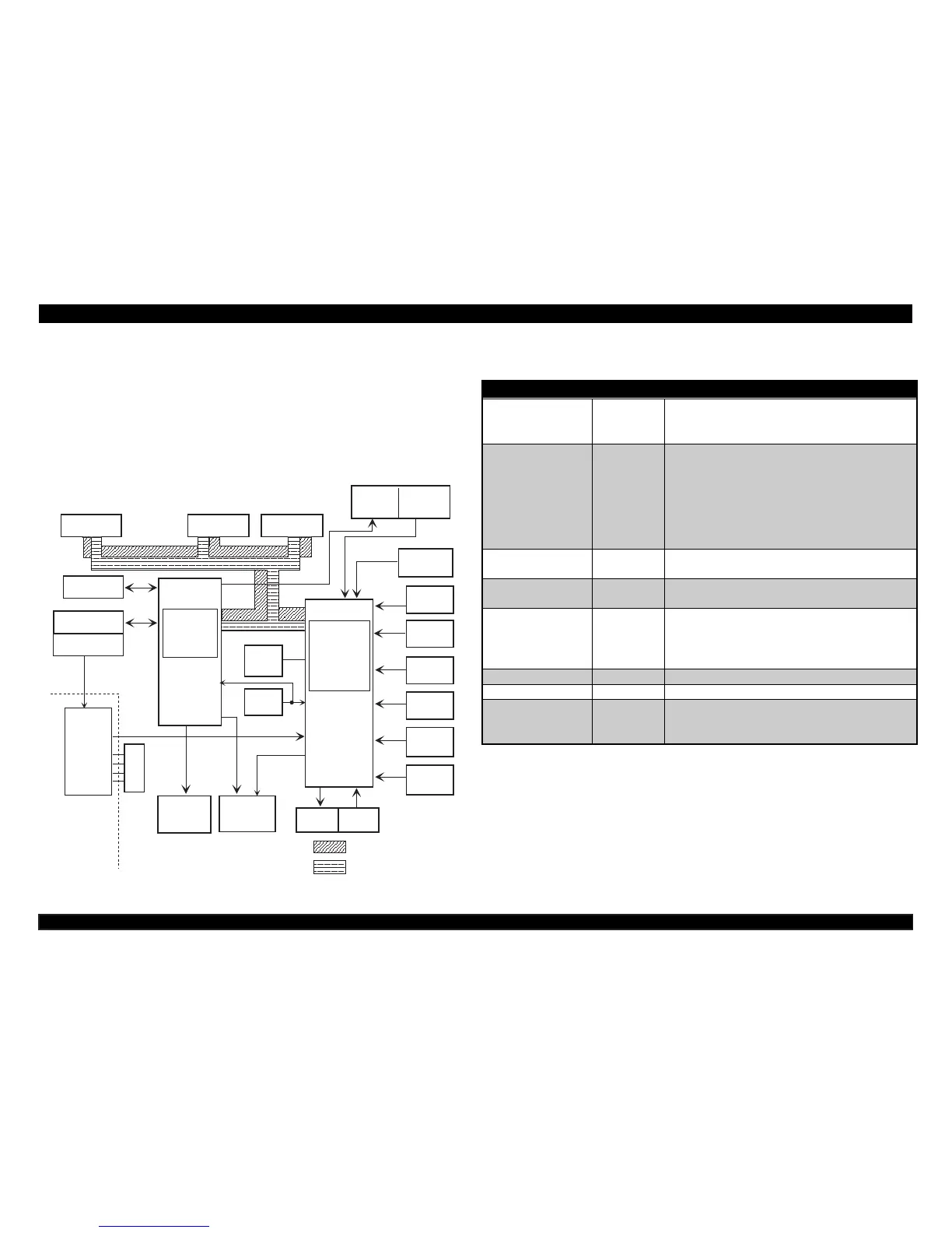
other circuits. This control circuit oversees control of all the components in
the printer. The following chart shows the control circuit block diagram.
G a te A rra y
CPU
CSF Drv.
CSF
Detector
P E -R ear
Detector
P E -F ro n t
Detector
TO P
Detector
Hom e
Detector
Release
Lever
Detector
Gap
Lever
Detector
+35V V oltage
Detector
Head Drv.
H ead Tem p.
Detector
EPROM
PS-RAM
or S R A M
Serial
EEPROM
R e s t IC
PF Drv. CR Drv.
Panel SW / LEDs
O perate S W
P a r a lle l I/F
Type B I/F
5V
GL
35V
GP
IC 2
IC 1
E05B 50**
TM P 96C 141B F
Q2~Q19
IC 1 2
SLA 7024M
U D N 2917E B
IC 8
IC 1 5
: D a ta B u s
: Address Bus
IC 3
IC 5
PSC
PW DN
Pow er Supply
Board
IC 9
Figure 2-3. Control circuit Block Diagram
The functions of main components of control circuit on C244MAIN board are
shown on the following table.
Table 2-3. Functions of Main Components
IC Location Function
Gate array
(E05B50**)
IC1 Control the functions below;
• System control
• Peripheral device control
CPU
(TMP96C141BF)
IC2
• Receives data from the host computer
and send it to the input buffer in RAM.
• Extend the input data held in the buffer
to create Image data.
• Load image data to the image data
buffer.
• Transfer image data to the printhead.
1 / 4Mbit
PS-RAM
IC3 Buffer and working area
2Mbit PROM IC5 The ROM contains the program that runs
the CPU and character tables.
Serial EEPROM
(AT93C46)
IC8 Contains following data;
• Default setting values
• Market data
• Mechanism & printhead parameter, etc
SLA7024M IC9 CR motor drive IC
A2917SEB IC12 PF motor drive IC
Reset IC
(BH6150F)
IC15 This IC generates the reset signal at power
on or down, and makes reset the CPU and
the gate array.
 Loading...


