FX-2180 Service Manual Troubleshooting
Rev. A
3-1
3.1 OVERVIEW
This chapter contains flowcharts and check point tables that are helpful for
troubleshooting the printer. The flowcharts facilitate identifying faulty units
or parts from abnormal symptoms. The checkpoints provides unit
characteristics, such as resistance, continuity, and so on, to which you can
refer when isolating faulty units or parts.
3.2 TROUBLESHOOTING INFORMATION
This section describes troubleshooting information to let you find the point
of replaceable unit or part.
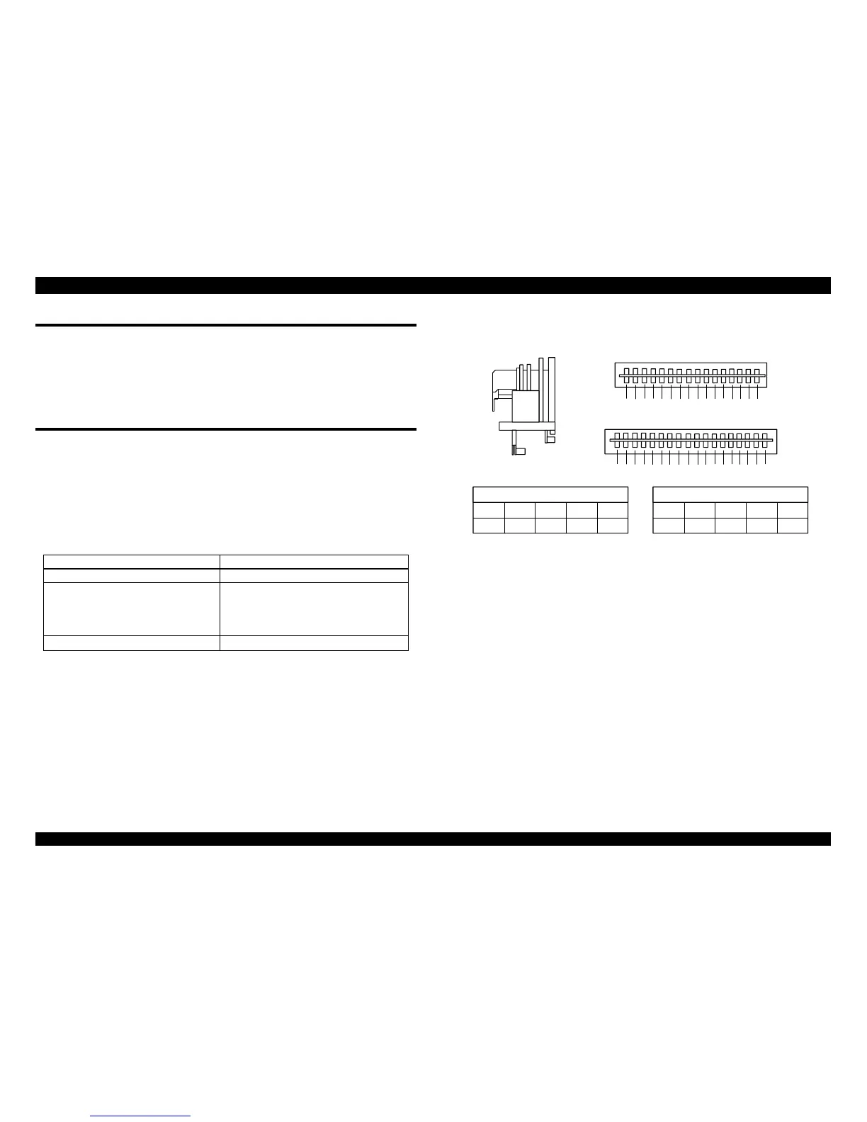
3.2.1 Printhead
It is easy to check if a printhead is defective or not. Referring to the
following table and figure, measure the printhead coil resistance and check
if it is correct
Table 3-1. Printhead coil Resistance Test Points
Common Pin No Refer to the following figure.
Test Pin No. Refer to the following figure.
Test Method
(Set meter to ohms. Disconnect
the printhead after the printer is
powered off.)
Place one lead on each pin and
the other lead on each common
pin.
Meter Reading
± 1.64 Ω (at 25°C)
3 15C52C65
16 11
C7
17
C8 14 4 8
1
9
13
7
C1
18 C2
12
C3
C4
610
TT
XX
X
X
XX
R
F
R
F
F
COM. C1 C2 C3 C4
1, 7, 13 9 10, 18
6, 12
R
COM. C5 C6 C7 C8
2, 5, 11
3, 15 16, 17
4, 8, 14
Pin No, Pin No,
T : Thermistor terminal
X : Not used
Figure 3-1. Printhead Connenctor Pin Alignment

 Loading...


