4.2.9.5 Disassembling the Right Frame Assembly
1. Remove one CBS screw (3 × 6) and one CBS screw (3 × 8) securing
the right sub frame. (The bold line in the illustration is the right sub
frame.)
2. Remove the right sub frame from the right frame.
R ight Sub Fram e
C B S (3 x 6)
C B S (3 x 8)
Figure 4-21. Removing the Right Sub Frame
CHECK POINT
9
The tightening torque for the CBS screws (3 ×× 6)
and (3 ×× 8) : 0.78 ∼∼ 0.98 Nm (8 ∼∼ 10 Kgf-cm)
The tightening torque for the hexagon nut : 1.18
∼∼ 1.37 Nm (12 ∼∼ 14 Kgf-cm)
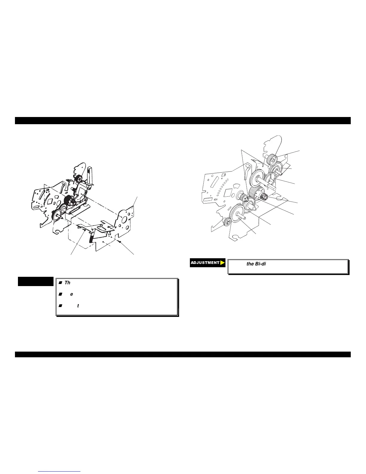
Mount the 11 parts above on the right frame
assembly, as shown in the following figures.
C om pression S pring 200 and
Plain W asher
Spur G ear 34.5
Spur G ear 21
Spur G ear 34.5
C om bination G ear 8/31.5
In te rm itte n t G e a r
Spur G ear 27
Spur G ear 34
Figure 4-22. Engaging Gears 1
$'-8670(17
Adjust the Bi-directional print alignment. (Refer to
chapter 4.)

 Loading...


