3.2.2 Detectors
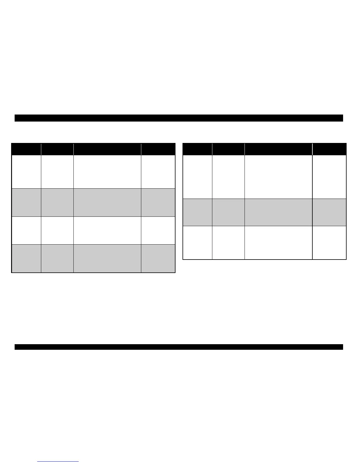
Table 3-2. Detector Test Point
Detector
CN No.
Test Pin No.
Test Method
(Set Meter to DC Voltage)
Meter
Reading
CN4
(HP
Detector)
1 : HP
2 : GND
3 : +5V
Place one lead on pin 1 and
the other lead on pin 2, and
check the voltage while
blocking two detector
terminal.
• Open : +5V
(Home
position)
• Short : 0V
(Out of
home)
CN5
(Rear PE
Detector)
1 : +5V
2 : PE
3 : GND
Place one lead on pin 2 and
the other lead on pin 3, and
check the voltage while
toggling the detector lever.
• Open : +5V
(Paper
loaded)
• Short : 0V
(No paper)
CN6
(Front PE
Detector)
1 : PE
2 : GND
Place one lead on pin 1 and
the other lead on pin 2, and
check the voltage while
toggling the detector lever.
• Open : +5V
(Paper
loaded)
• Short : 0V
(No paper)
CN7
(TOP
Detector)
1 : E
2 : GND
3 : +5V
4 : A
Place one lead on pin 1 and
the other lead on pin 2, and
check the voltage while
inserting and removing paper
between the detector.
• Open : 0V
(No paper)
• Short : +5V
(Paper
loaded)
Table 3-3. Detector Test Point (continue.)
Detector
CN No.
Test Pin No.
Test Method
(Set Meter to DC Voltage)
Meter
Reading
CN12
(Release
Detector 1 /
2)
1 : Release 1
2 : GND
3 : Release 2
4 : GND
Place one lead on pin 1 and
the other lead on pin 2, and
check the voltage while
toggling the release lever.
Place one lead on pin 3 and
the other lead on pin 4, and
check the voltage while
toggling the release lever.
• Open : +5V
• Short : 0V
CN13
(PG
Detector 1/
2)
1 : PG1
2 : GND
3 : PG2
4 : GND
Place one lead on pin 1 and
the other lead on pin 2, and
check the voltage while
toggling the PG detector
lever.
• Open : +5V
• Short : 0V
CN2 on
Panel
board
(Case
Open
Detector)
1 : COPEN
2 : GND
Place one lead on pin 2 and
the other lead on pin 3, and
check the voltage while
toggling the detector lever.
• Open : +5V
(Case
opened)
• Short : 0V
(Case
closed)

 Loading...


