4.2.9.8 Removing the CR Assembly
1. Remove the printer cover, the rear / front edge guide assemblies, front
cover, paper eject assembly, and rear / fronts tractor units. (Refer to
Section 4.2.1.)
2. Remove the panel board assembly. (Refer to Section 4.2.2.)
3. Remove the upper housing assembly. (Refer to Section 4.2.7.)
4. Remove the printer mechanism. (Refer to Section 4.2.9.)
5. Remove the left frame assembly. (Refer to Section 4.2.9.6.)
6. Removing the RD assembly. (Refer to Section 4.2.9.7.)
7. Disconnect 3 FFCs from the printhead and PW sensor assembly.(Refer
to Section 4.2.5.)
FFCs
PW Sensor Assem bly
CB(2x5)
Figure 4-28. Disconnect the FFCs
8. Disengage the timing belt from the CR motor pinion gear.
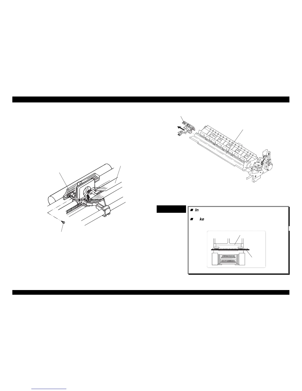
9. Remove the CR assembly from the rear/front CR guide shaft.
CR Assem bly
Rear CR Guide Shaft
Figure 4-29. Removing the CR Assembly
10. Remove the timing belt from the 2 holding slots under CR assembly.
11. Remove the CR assembly.
CHECK POINT
9
Insert the timing belt properly into the 2 holding
slots at the bottom of the CR assembly.
Take up this timing belt slack between the two
slots completely, as shown in the following
figure;
Tim ing B elt
CR Assembly
Figure 4-30. Inserting the Timing Belt

 Loading...


