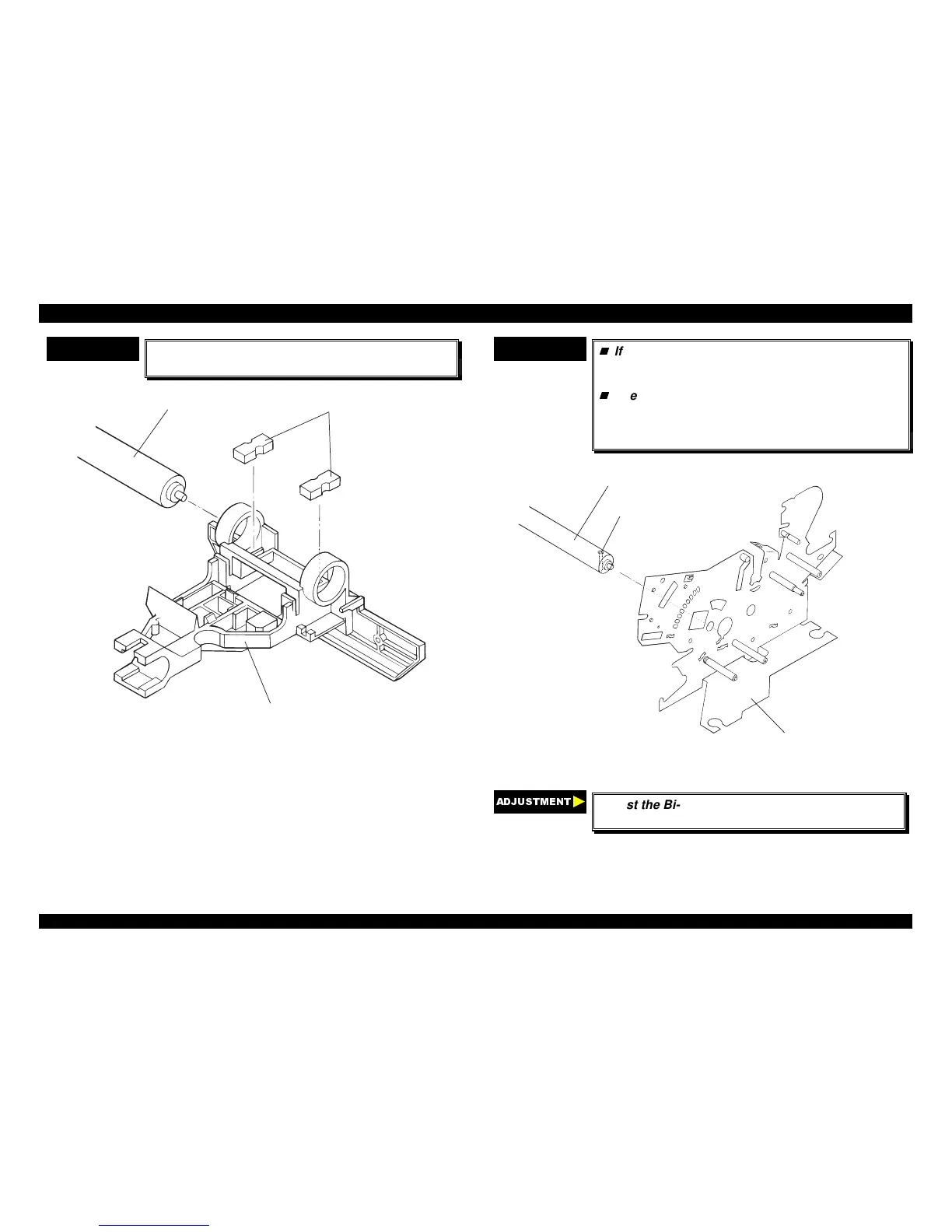
CHECK POINT
9
Insert the 2 oil pads into the proper position in the
CR assembly, as shown in the following figure;
Oil Pad
CR Assem bly
Rear CR Guide Shaft
Figure 4-31. Installing the Oil Pad in the CR Assembly
CHECK POINT
9
If remove the rear CR guide shaft along the CR
assembly once, be sure to reinstall the rear CR
guide shaft in the printer mechanism.
The rear CR guide shaft has been a drilled
through hole near the right edge, and one side
of the hole has a chamfered edge. This edge
should be up, as shown in the following figure;
Left Fram e Assem bly
C ham fered hole
C R G uide S haft
Figure 4-32. Assembling the Rear CR Guide Shaft
$'-8670(17
Adjust the Bi-directional print alignment. (Refer to
chapter 4.)
 Loading...


