FX-2180 Service Manual Appendix
Rev. A
7-1
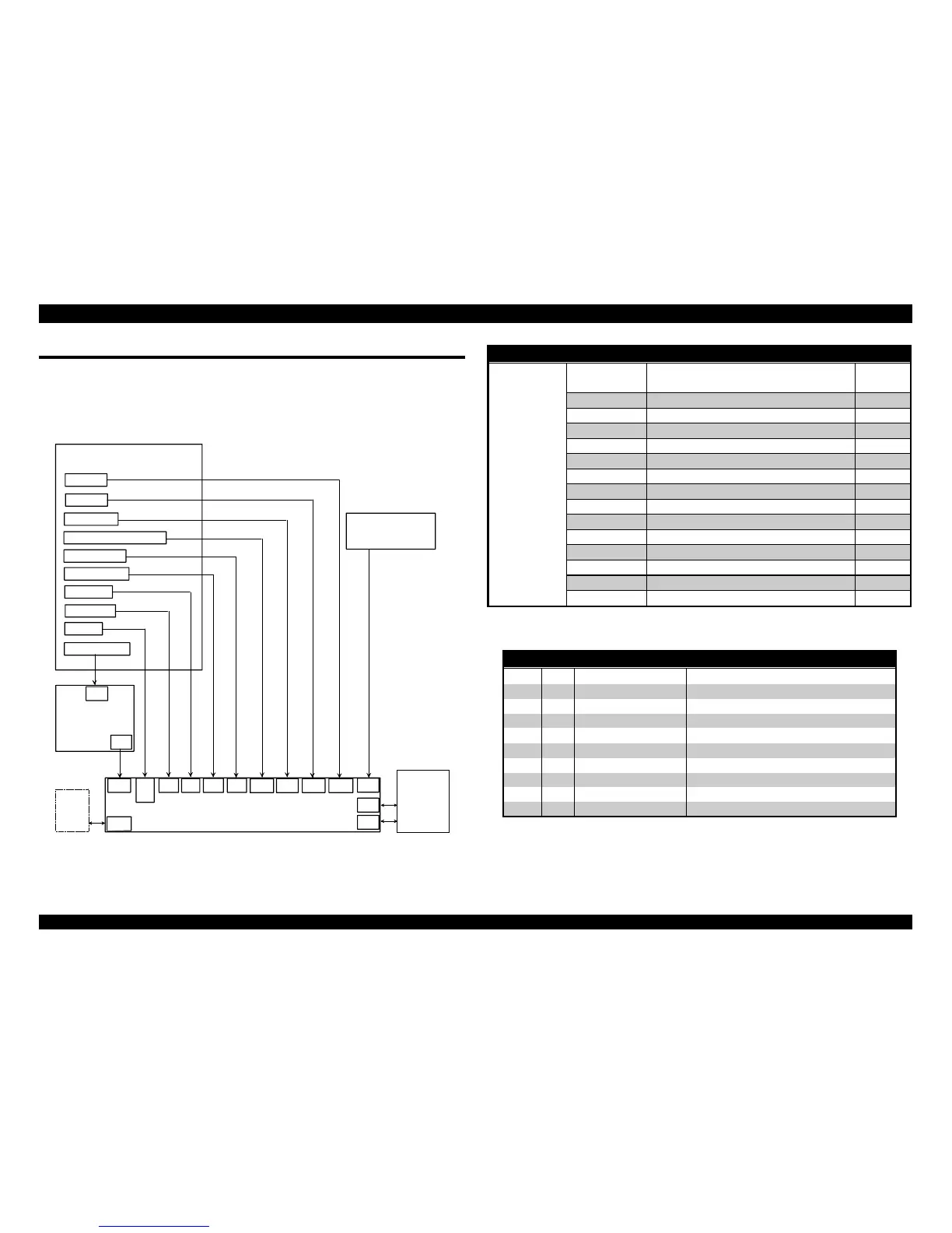
7.1 CONNECTOR SUMMARY
The following figure shows the connector connections of main components.
And, the following table shows the summary of function s and sizes of the
connectors.
Printer Mechanism
PG Detector
Release Lever Position Detector
Rear PE Detector
Front PE Detector
HP Detector
TOP Detector
Printhead
C244 MAIN Board Assy.
CN13
CN5
CN6
CN4
Case Open Detector
C166 PSB / PSE,
C244 PSH Board Assy.,
CN3CN12
CN7
CN8
CN9
PF Motor
CR Motor
CN11 CN10CN15
CN2
CN1
PNL Board Assy.
CN14
CSF
Bin 1
CN1
Host
Computer
Parallel I/F
CN2 Option I/F
Figure 7-1. Main Components Connections
Table 7-1. Connector Summary
Board Connector Function Pins
Main Board
Assy.
CN1 Parallel Interface 36
CN2 TYPE-B Interface 36
CN3 Power Supply Board 10
CN4 HP Sensor 3
CN5 Rear PE Sensor 3
CN6 Front PE Sensor 2
CN7 TOP Sensor 4
CN8 Printhead 18
CN9 Printhead 16
CN10 PF Motor 4
CN11 CR Motor 5
CN12 Release Lever Position Sensor 4
CN13 PG Sensor 4
CN14 CSF Bin 1 10
CN15 PNL Board 22
Table 7-2. Connector Pin Alignments - CN3
Pin I/O Signal Name Function
1
GP
2
GP
3 I +35V +35VDC
4 I +35V +35VDC
5
GND Signal Ground
6
GND Signal Ground
7 I +5V +5VDC
8 I +5V +5VDC
9 I PWDN Power Down detection signal
10 O PSC Power switch on/off signal

 Loading...


