4.2.3 Removing the Printhead
1. Remove the printer cover and ribbon cartridge. (Refer to Section 4.2.1.)
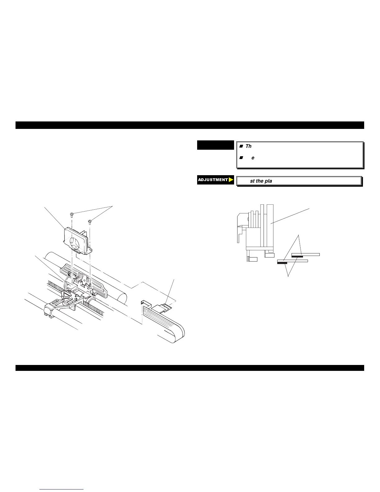
2. Remove two CBS screws (3 × 10)securing the printhead to the CR
assembly.
3. Remove the printhead from the CR assembly.
4. Disconnect two wide FFCs from the printhead and then disconnect the
narrow FFC from the connector on the CR cover.
CBS (3x10)
Printhead
FFCs
CR Assem bly
Figure 4-5. Removing the Printhead
CHECK POINT
9
The FFC must be connected properly, as shown
in the following figure.
The tightening torque for the screws : 0.59 ~
0.78 Nm (6 ~ 8 Kgf-cm)
$'-8670(17
Adjust the platen gap. (Refer to Chapter 5.)
F F C s fo r P rin th e a d
D irection in w hich the explosed term inals faces
Print H ead
Figure 4-6. Method for Connecting the Printhead FFC

 Loading...


