FX-2180 Service Manual Disassembly and Assembly
Rev. A
4-21
4.2.9.7 Removing the Ribbon Drive (RD) Assembly
1. Remove the printer cover, the rear / front edge guide assemblies, front
cover, paper eject assembly, and rear / fronts tractor units. (Refer to
Section 4.2.1.)
2. Remove the panel board assembly. (Refer to Section 4.2.2.)
3. Remove the upper housing assembly. (Refer to Section 4.2.7.)
4. Remove the printer mechanism. (Refer to Section 4.2.9.)
5. Remove the left frame assembly. (Refer to Section 4.2.9.6.)
6. Remove two CBS screws (3 × 8) securing the RD assembly to the front
frame.
7. Remove the RD assembly from the front frame.
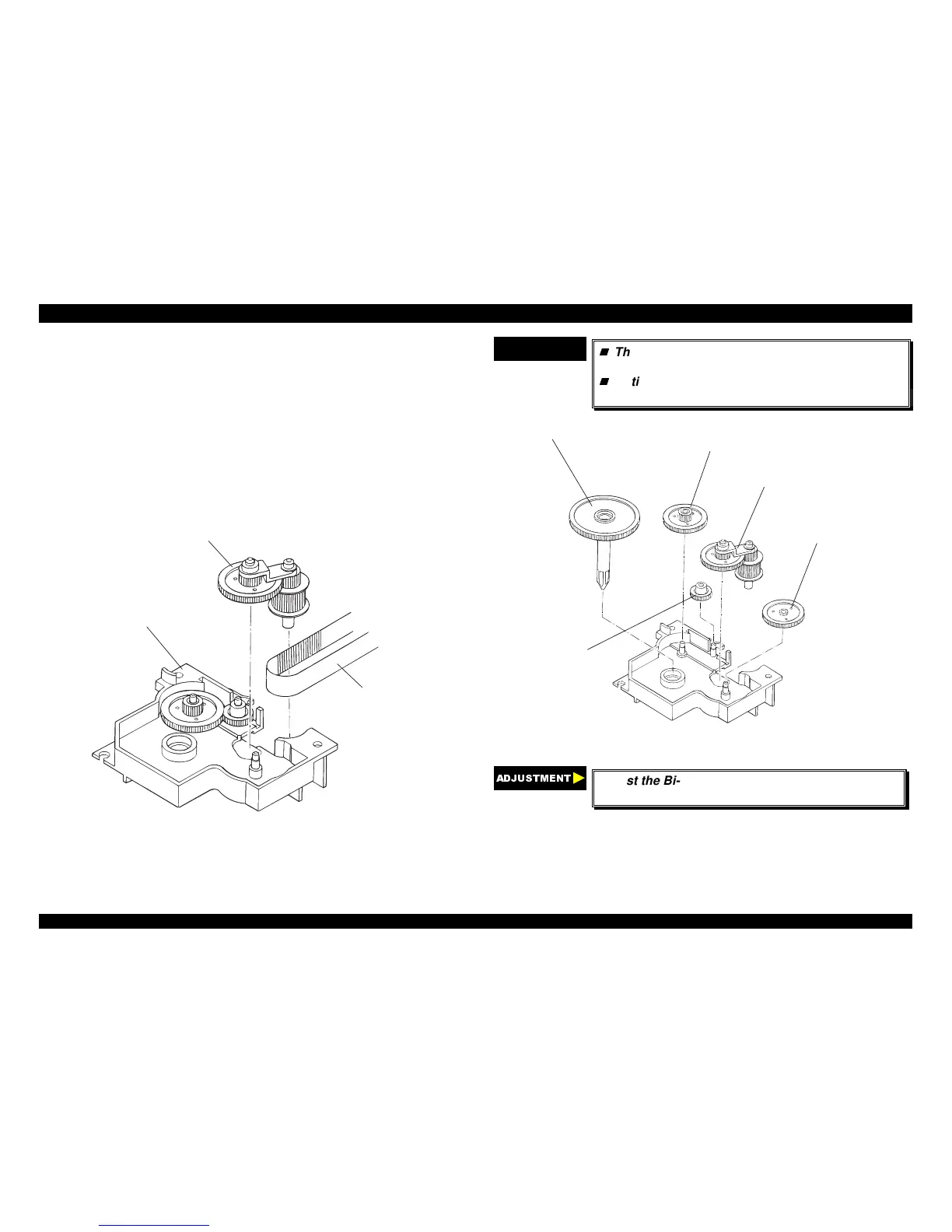
8. Remove the timing belt from the DR assembly.
D r iv e n P u lly A s s e m b ly
RD Assembly
Tim ing Belt
Figure 4-26. Removing the RD Assembly
CHECK POINT
9
The tightening torque for the CBS screws (3 ×× 8)
: 0.78 ∼∼ 0.98 Nm (8 ∼∼ 10 Kgf-cm)
Notice how the gears in the RD assembly are
engaged as shown in the following figure;
R a c h e t,R D
C om bination G ear 7/23
D r iv e n P u lly A s s e m b ly
Spur G ear 25
Spur G ear 11
Figure 4-27. Engaging Gears for the RD Assembly
$'-8670(17
Adjust the Bi-directional print alignment. (Refer to
chapter 4.)
 Loading...


