REV.-A
4.2.5 Printer Mechanism Disassembly
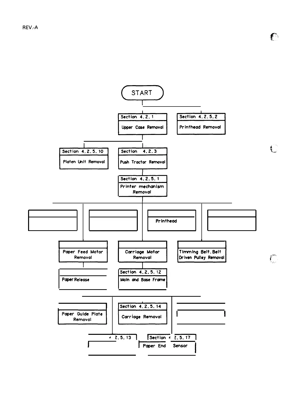
This section describes the procedures for disassembling the main components of the printer
mechanism. Figure 4-14 shows the relationship of the printer mechanism’s major components for
reference during assembly.
Refer to Figures A-20 through A-25 in the Appendix during assembly.
=
Section 4.2, 5.1
Printer
mechonism
Removal
I
I
I
I
b
Section 4,2, 5,9
Section 4.2,5.6 Section 4.205.3
section 4
0
2.5,8
Plunger Removal
Home Position Sensor
Printheod
FPC
Friction/Troctor
Removal Removal
Sensor Removal
A
1
Section 4.2, 5,7
I
Section 4.2.5.11
1
Pqwr
Releose
Lever
Removal
I
I section 4,2,5.15
I
1 Section
~
n
Section 4,2,5.4
I
=?=J
Removal
I
t
Section 4,2.5.5
1
I
I Section 4.2, 5.16
1
I
Paper Feed Roller
I
Removal
I I
1
-nd
sensor
I
I Ribbon Driver
I
Removal
II
Removal
I
F“;
-., .
-.,—.
i
.
..
.
.
.
.
Figure 4-14. Printer Mechanism’s Component Relationship
4-12

 Loading...


