REV.-A
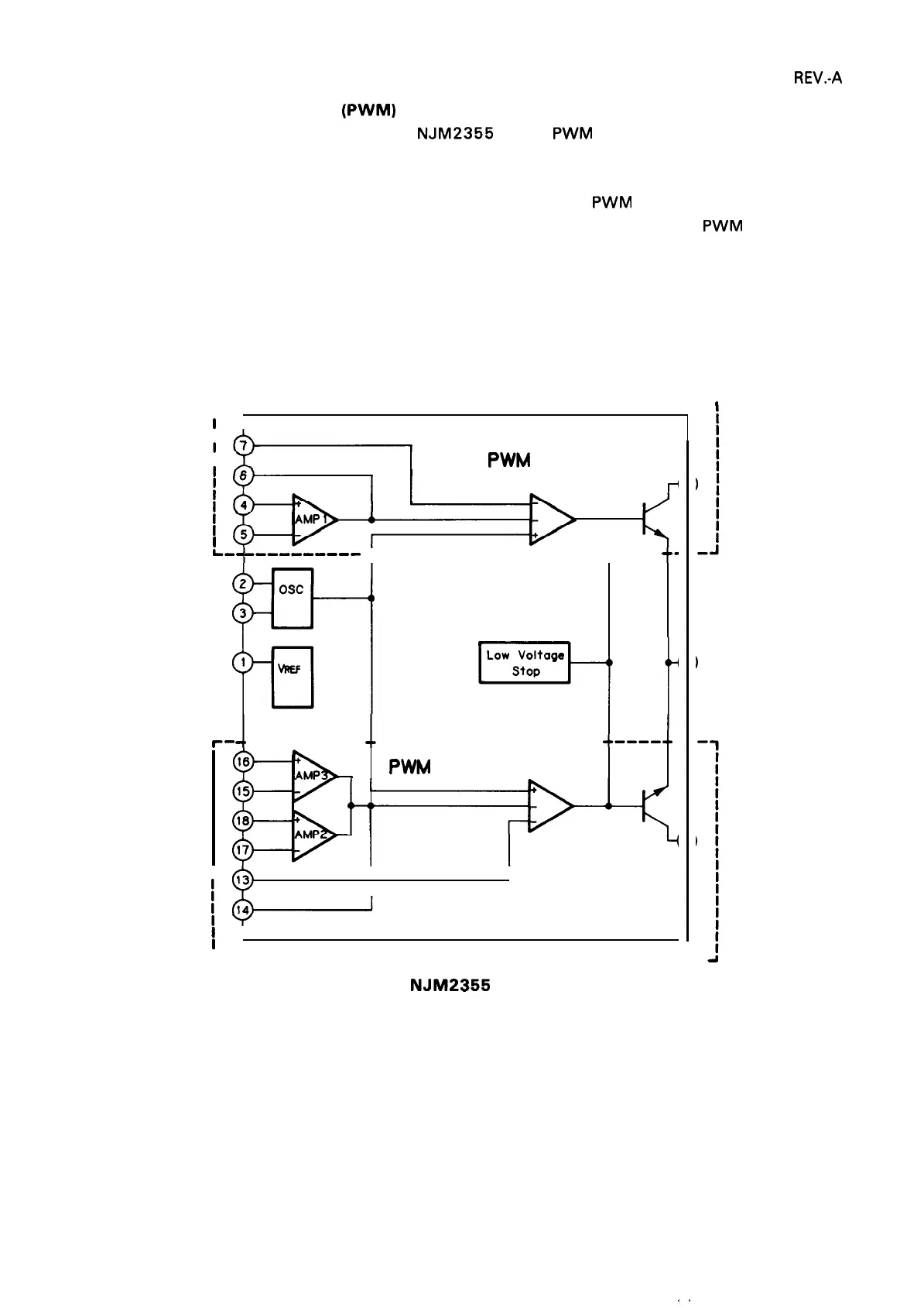
2.3.2.5 Pulse-Width Modulation
(PWM)
Circuit
Figure 2-16 shows the internal circuit of the
NJM2355
IC. The PWM comparator operates as follows:
In circuit 1 the output from AMP 1 flows into the negative terminal of comparator 1, and the outputs
from AMP 2 and AMP 3 in circuit 2 flow into the negative terminal of
PWM comparator 2 without wired
OR. Dead-time control voltage is also input to additional negative terminals of both
PWM comparators
1 and 2.
A sawtooth waveform from the oscillator is input to the positive terminals. The sawtooth waveform from
the oscillator causes the comparators to generate pulses as shown in Figure 2-17.
Circuit 1
r
-----------------------------------------
1
i
I
I
I
I
PWM
Comparator 1
I
I
I
I
-t
h-
----.-----
------------------- ----
+
t
+-
1%1
2
Osc
3
1%
-1
J
Circuit 2
J1
r-
---------- ------------------- ---- -
PWM
Comparator 2
I
I
I
I
I
I
L
-----------------------------------------
i
Figure 2-16,
NJM2355
Internal Circuit
2-19

 Loading...


