REV.-A
2.3.2.1 Filter Circuit
<.,.
%
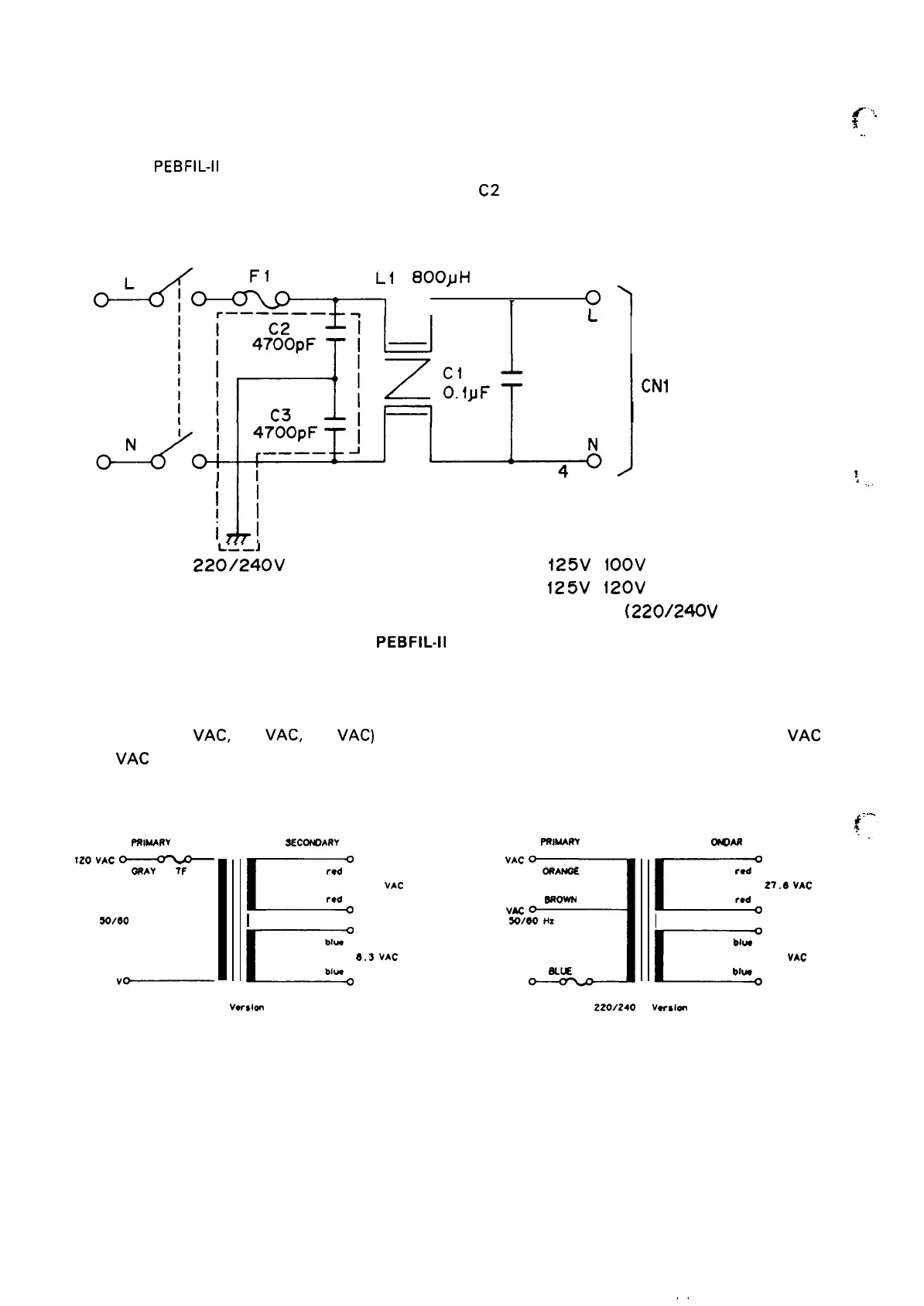
The AC line voltage passes through the power switch, then is input to the filter circuit. A fuse, F1, is
““
used on the
PEBFIL-11
board. The filter circuit attenuates external noise and inhibits noise generated
in the printer from going out via the AC line. Either C 1 or
C2
drains leakage current between the primary
coil and the case. Figure 2-1 1 shows the filter circuit.
O&fi-C&.,
LI
800}H
1
.——————
.
I
1
“)
1
L
J
ii
I
1]
-—
(
22~/240V
Version Only)
F 1
:
2A
125V
( iOOV Version
2A
125V
(
120V
Version
1.25A 250V
(220/240V
)
)
Version)
Figure 2-11.
PEBFIL-11
Filter Circuit Board
2.3.2.2 Transformer
AC Voltages(120
VAC,
220
VAC,
240
VAC)
that pass through the filter circuit are divided into 26
VAC
and 12
VAC
and supplied to the PEGX circuit. Figure 2-12 shows a schematic drawing of the power
transformer.
FRlb4ARY
IZO
vAC
~
ORAY
7F
S0/00
Hz
WHITE
o
v~
2ECOtOARY
FRIMARY
E
red
27.6 VAC
red
c
blue
8.3
VAC
NW
240
VAC
3
ORANOE
wow
220
VAC
S0/00 HZ
BLLE
Ov
E
red
27.6
VAC
red
E
blw
8.3
VAC
blw
TF
IZOV
Verslan
ZZO/240
V Varslm
Figure 2-12 Transformer Circuit
2-16

 Loading...


