REV.-A
Carriage Carriage Guide Shaft A
I
Carriage Guide Shaft B
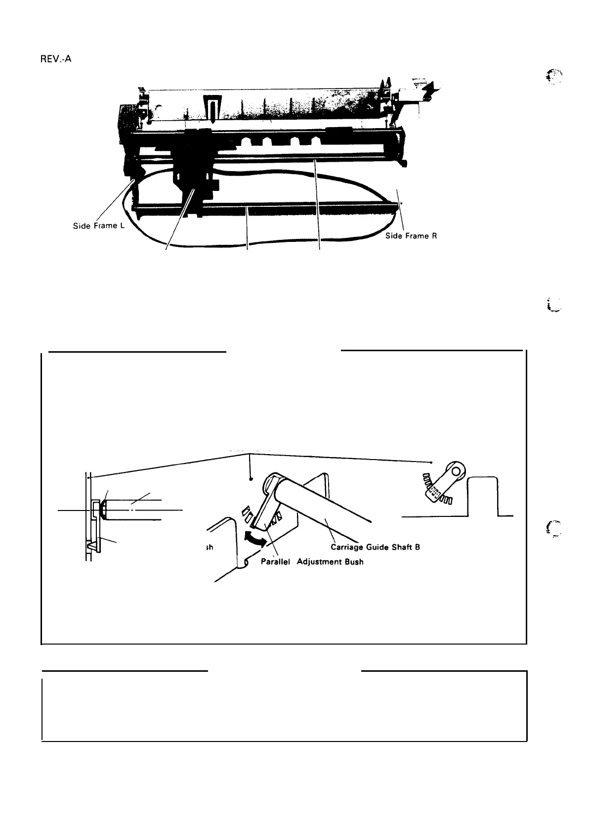
Figure 4-41. Carriage Guide Shafts A and B Removal
Step 7:
Pull
the carriage out from the carriage guide shafts A and B.
ASSEMBLY POINTS
1. While passing the carriage guide shaft B through the carriage, fit the felt to the bottom of the
carriage.
2. Set one LS (6 X 0.15 X 1 1) and the parallel adjustment bush to the right side of the carriage
guide shaft B.
NOTE: LS and parallel adjustment bush has direction, set as shown in Figure 4-42.
Side Frame R
LS
Carriage Guide Shaft B
r
7
Parallel Adjustment Bush
II
~
Pa~allel
AdjustmentBush
Figure 4-42. LS and Parallel Adjustment Bush Removal
3. Adjust the parallel adjustment bush where the printhead moves along the platen in parallel.
I
ADJUSTMENTS REQUIRED
For assembly, the following adjustments are required:
4.3.1 Platen Gap Adjustment
4.3.2 Paper Feed Motor Backlash Adjustment
i-;.
~.--,
.-.,
,
4-30

 Loading...


