REV.-A
The power supply circuit is divided into the
PEGX
board,
PEBFIL-11
board, and power supply transformer.
This circuit converts the AC voltage from the step-down transformer into the DC voltage required to
drive the printer mechanism and operate the control circuits. The AC voltage from outside the printer
is input to the step-down transformer via the filter circuit. The AC voltage is converted to 26
VAC
and
12
VAC
by the transformer, and is input to the power supply circuit on the
PEGX
board.
The 26
VAC
is converted to approximately 36 VDC by the full-wave rectifier and smoothing circuit. The
unregulated DC voltage and the regulated +24
VDC and + 5 VDC (total of 3 supplies) are supplied to
the control circuit. Switching regulator IC NJ M2355 (1A) controls the chopper-type switching regulator
circuits for +24
VDC and +5
VDC.
The +36 VDC and +5 VDC are supplied to the Vx voltage circuit, converted to the Vx voltage, and
supplied to the reset circuit.
The 12
VAC
is converted to unregulated 12 VDC by the positive half-wave rectifier and the smoothing
circuit, and is supplied to the control circuit.
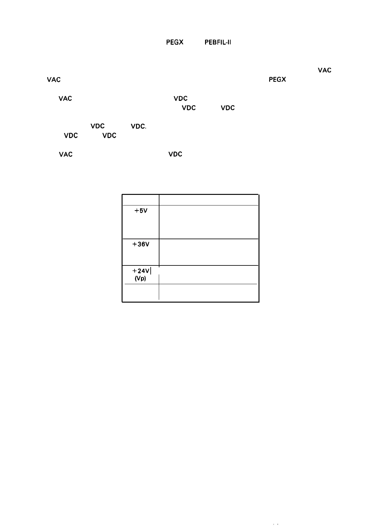
Table 2-2. Power Supply Application
Voltage
Application
+5V
Logic circuit
Plunger solenoid holding voltage
Paper feed motor holding voltage
Signal pull-up voltage
+36V
Plunger solenoid driving voltage
(vu)
Paper feed motor driving voltage
Carriage motor driving voltage
+24V
I
Printhead driving voltage
(Vp)
Option interface voltage
+ 12V
Option interface voltage
- 12V
2-11

 Loading...


