EPSON PowerLite 5000 Service Manual
2-9
2.3 MAIN BOARD
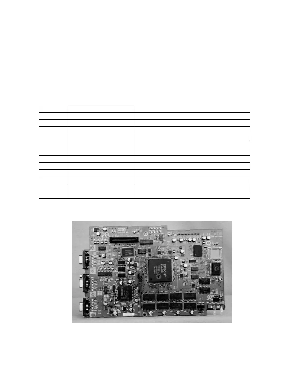
The main board consists of the CPU, P-ROM, video memory (SRAM), digital video
controller, and circuits to control the control panel, computer input interface, monitor
output, speakers, power management, etc. The main board controls everything except
video signal generation. The main board is available as a unit for service. The fuses listed
below are soldered onto the main board and are for reference only.
Table 2-4 Main Board Fuses
Fuse Specifications Purpose
FB300 BLM41A8005 (A) +12 V Monitor circuit
FB316 BLM41A8005 (A) +12 V Video input A/D circuit
FB317 BLM41A8005 (A) +12 V Computer IN 1/2 circuit
FB318 BLM41A8005 (A) +12 V ADC for Computer IN 1/2
FB802 BLM21B201S (A) LPST
FB806 BLM41A8005 (A) BACTA
FB807 BLM41A8005 (A) PWDS
FB808 BLM41A8005 (A) STFIL
FB809 BLM41A8005 (A) LSTAT
FB810 BLM41A8005 (A) LV thermistor
FB811 BLM41A8005 (A) Lamp thermistor
FB812 BLM41A8005 (A) PBS thermistor
Figure 2-8