EPSON PowerLite 5000 Service Manual
2-21
The signals from the receptor board (FI board/RI board) are sent to the FR board and are
used for wireless mouse control (controlling the host computer via the remote control).
The signals from the filter cover switch are sent to the main board. If the filter cover is
open, power cannot be supplied. The signals for controlling serial operations and the
receptor board signals are sent from the FR board to the CN board.
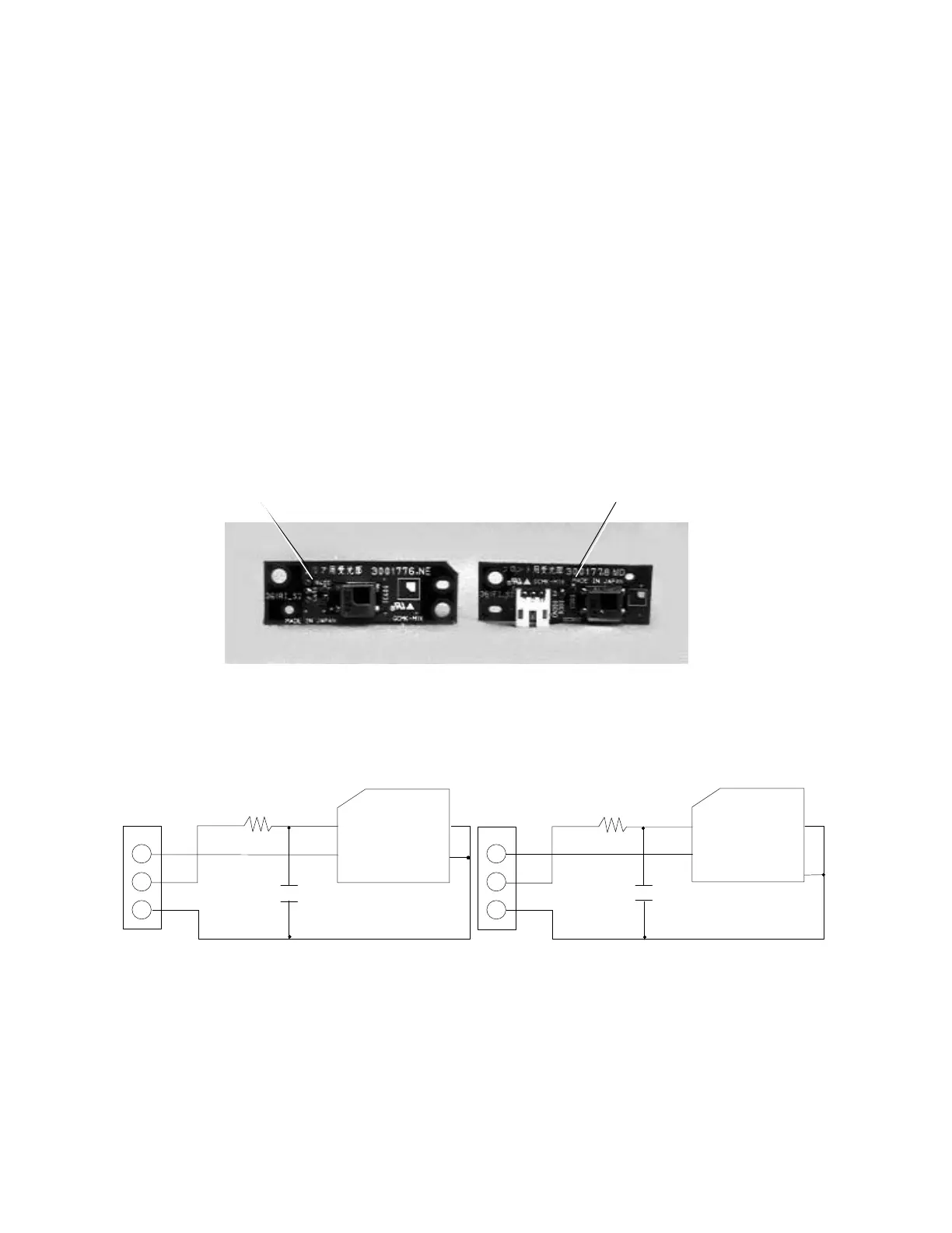
2.9 RECEPTOR BOARD (FI/RI BOARD)
This board detects infrared signals. This unit consists of two receptor boards: one is
attached to the speaker bracket on the front face (FI board), and the other is on the rear
case (RI board). You can control this device on both sides. The FI and the RI are different
in shape, but the same in function (circuit).
Receptor Boards and Their Circuits
RI board (rear) FI board (front)
Figure 2-19
FI Board Circuit RI Board Circuit
Figure 2-20
Each receptor board is connected to CN203/204 on the connector board. Each board’s
output signal (serial data) is connected to CN802 on the main board via CN200 after wired
OR is applied.
47
2
2 1
1
2
361FI
GP1U102X
S38-PH-K
GNDVCC1
1 4
GNDVOUT
11
2
3
0. 1U
16 V
2
1
CHIP
33
F
2
361RI
GP1U102X
B38-PH-K-S
47
GNDVCC1 4
GNDVOUT
1
3
0. 1U
16 V
22
1
CHIP
33
F
2