EPSON PowerLite 5000 Service Manual
1-18
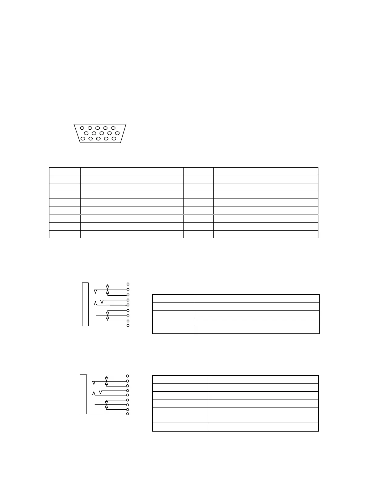
1.6 INTERFACE SPECIFICATIONS
1.6.1 Computer In 1/2
Computer video input D-SUB 15 (HD)
Table 1-3
Pin Terminal Pin Terminal
1 Red video 9 +5V
2 Green video 10 Synchronous GND
3 Blue video 11 Monitor (ID bit 0)
4 Monitor (ID bit 2) 12 SDA
5 GND 13 Horizontal synchronization
6 Red video GND 14 Vertical synchronization
7 Green video GND 15 SCL
8 Blue video GND
1.6.2 Audio In 1/2
Stereo mini jack with 2 circuits for detection pin
(The detection pin, which is not required for audio input, is installed for the audio out terminal.)
Table 1-4
Pin number Signal
1 GND
2 Computer audio input L
3 Computer audio input R
Others NC
1.6.3 Audio Out
Stereo mini jack with two circuits for detection pins
Table 1-5
Pin number Signal
1 GND
2 Audio output L
3 Audio output R
4 GND
5 Detection of line-out jack insertion
Others NC
15 11
Figure 1-32
Figure 1-33