EPSON PowerLite 5000 Service Manual
3-10
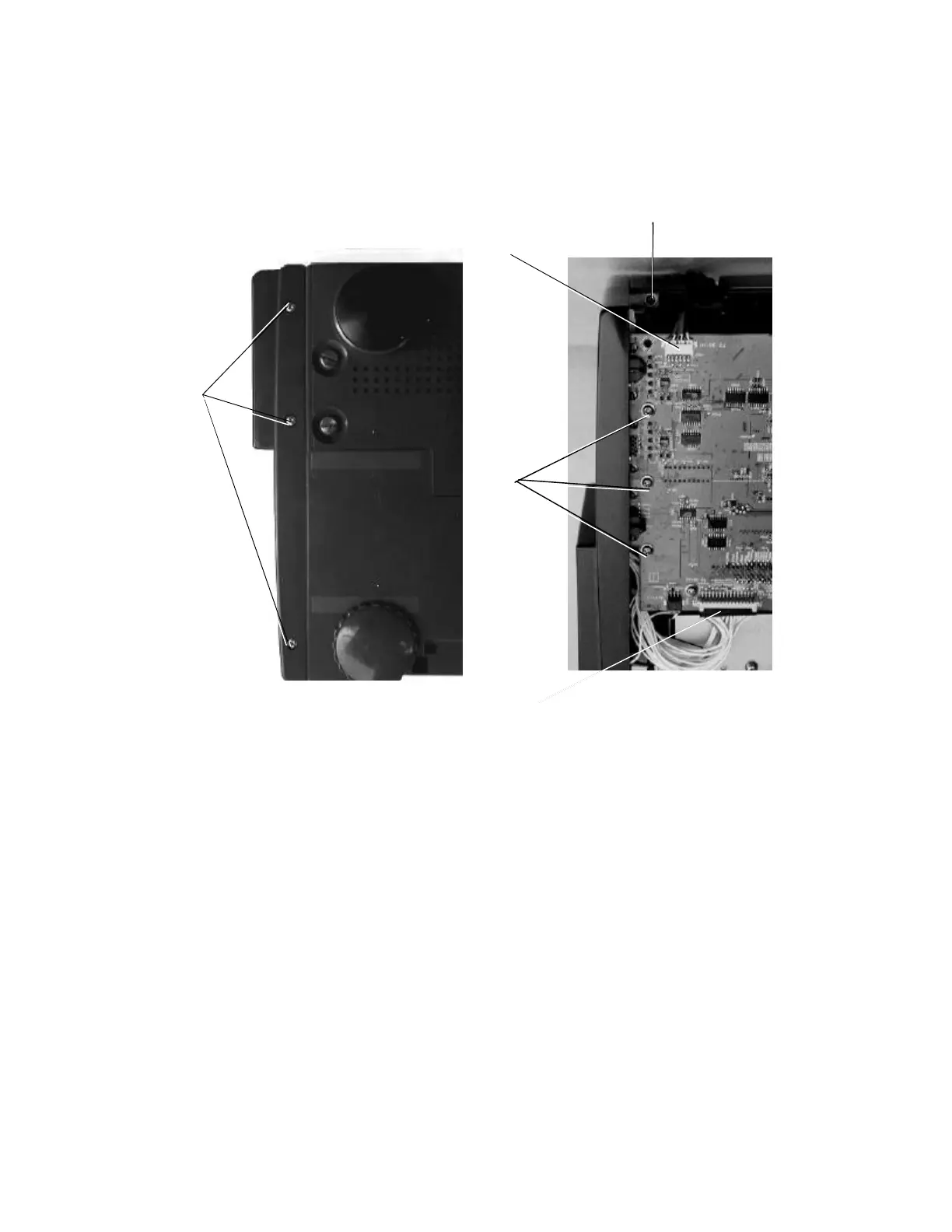
3.2.4 Removing the Rear Case Unit Assembly
Prerequisite condition: 3.2.3
1. Remove 3 screws mounting the rear case to the bottom of the lower case.
Screws: +M3×8 F/ZB: P/N 1033691
(mounting torque: 6.0 kg. cm = 5.2 lb. inch)
2. Remove 3 screws mounting the main board to the audio board shield plate, and the
screw on the AC inlet hold plate.
3. Disconnect connectors CN300/CN603 on the main board.
4. Remove the cable from the RI board connector (the RI board connector is mounted on
the rear case unit.)
5. Remove the 6 hex nuts from the Computer In and Computer In2 monitor ports.
6. Grasp both sides of the rear case unit, then gently pull it out a short distance.
7. Remove the screw holding the blue wire to the AU board.
8. Remove the rear case.
Caution:
When installing the case unit assembly, push it slowly.
Screws
CN300
CN603
Screws
Screw
Figure 3-9
Figure 3-10