EPSON PowerLite 5000 Service Manual
3-5
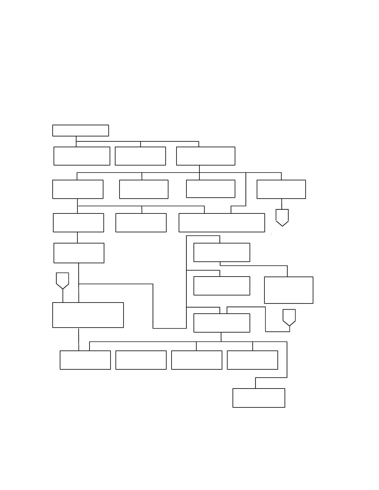
3.2 Disassembling and Assembling the Projector Main Unit
The flowchart for disassembling the projector main unit is shown below. You can
reassemble dismantled projector parts by reversing the order of disassembly. Therefore
unless specified, this manual contains no assembly procedures. Detailed descriptions of
disassembly procedures are given in sections 3.2.1 to 3.2.26.
Air Filter Frame
Upper Case Unit
FR Board
(3.2.11)
Foot Adjuster
(3.2.5)
Switch Panel
(3.2.6)
Left and Right
Speakers
Filter Cover
(3.2.21)
CN Board
(3.2.20)
Inlet Unit
(3.2.19)
Filter Board
(3.2.18)
Rear Case Unit
(3.2.4)
AU Board
(3.2.9)
Lamp Thermistor
(3.2.14)
Main Board
(3.2.8)
START
Lamp Inner
Housing (3.2.1)
Safety Switch
(3.2.16)
Optical Engine
(3.2.17)
FC Board
(3.2.22)
Power Supply
Unit/PBS Thermistor
(3.2.12)
A
A
A
Receptor BD (RI/FI Board)
(3.2.10)
Prism Duct/
LV Thermistor
(3.2.15)
Figure 3-1