EPSON PowerLite 5000 Service Manual
2-12
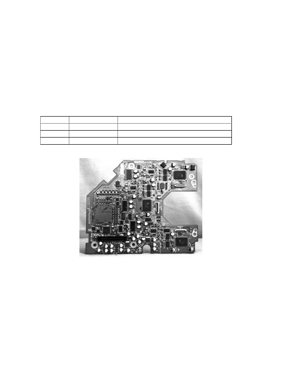
2.4 DRIVER BOARD
The driver board has two functions: one is converting the R/G/B display signal from the
main board into six states of analog signals (light valve driver signals) and the other is
controlling the display image by referencing electrical correction data.
The entire optical engine must be replaced in maintenance service. No individual parts,
such as the driver board, may be replaced. The fuses listed below are soldered onto the
Driver board. They are not replaceable and are listed for reference only. Please refer to
Section 3.1 for details.
Table 2-6 Driver Board Fuses
Fuse Specification Purpose
F250 4511.25 (A) +3.3 V
F251 4511.25 (A) +12 V
F252 CCP2E10 (A) +5 V
Figure 2-10
Functional Outline
• The signals RD 0~7, GD 0~7, and BD 0~7 output from the main board are first
converted into analog signals by the digital to analog converter before being output to