EPSON PowerLite 5000 Service Manual
2-20
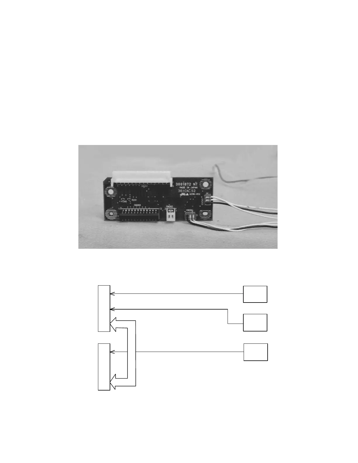
2.8 CN BOARD
The CN board is the relay board for the cable connector. It has five connectors. The
signals below are transferred to the main board through this board.
*FI board signal: Remote control signals go from the front receptor to the FR board.
*RI board signal: Remote control signals go from the rear receptor to the FR board.
*FC board signal: Filter cover detection switch signals go to the main board.
*FR board signal: Mouse / COM interface 1/2 signals go to the main board.
Figure 2-17
CN Board Connecting Block
CN
201
CN
200
CN203
CN204
CN202
Connects to
FR Board
CN101
Connects to
Main Board
CN802
Connects to
FI Board
(F Receptor)
Connects to
RI Board
(R Receptor)
Connects to
Filter Cover
Switch
Figure 2-18