EPSON PowerLite 5000 Service Manual
2-19
The ELP communication kit 2 option also enables the remote control to draw lines and
patterns on the screen.
The relay circuit (IC111 or IC116C) is switched to be able to accept the mouse encoder
signal and the button signal. Then the signals based on “Tracking +/- button” operation are
output to a host computer through the remote. The signals are transferred through the host
computer’s interface, and you can control (remote mouse controlling) the host computer
without its mouse.
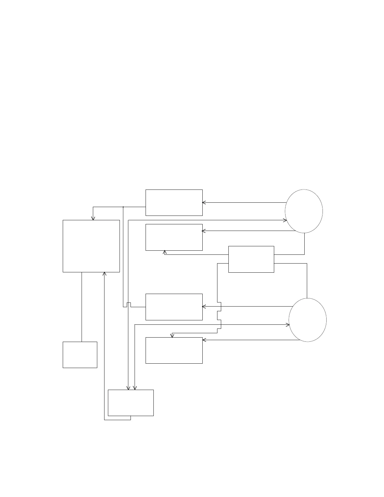
FR Board Circuit Block
Figure 2-16
Mouse/COM1
(CN100)
MDA0~7
Serial to parallel
(For Mouse1)
LEFT/RIGHT/CLOCK
13-PIN
TXD/RXD/DTR/DSR
Mouse/COM
Controller
Switching
(Mouse/COM1)
YA/TXD
Level
Converter
SEL
SEL
MDA
0~7
Serial to Parallel
(For Mouse2)
TXD/RXD/DTR/DSR
13-PIN
YA/TXD
Switching
(Mouse/COM2)
CN101
Mouse/COM2
(CN102)
Connects to
Main Board CN802
COM1/COM2
Level Converter