EasyManuals Logo

Epson PowerLite 5000 Service Manual

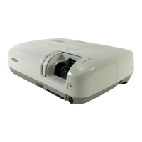
Epson PowerLite 5000
127 pages
To Next Page IconTo Next Page
To Previous Page IconTo Previous Page
Page #44 background imageLoading...
Page #44 background image
EPSON PowerLite 5000 Service Manual
2-14
Circuit Block Diagram of the Driver Board
B
Filter/Gate
F251 4511.25 A
+5 V REGULATOR
F250 4511.25 A
C
N
1
0
0
IC100
Display
Controller
F252CCP2E10 A
+3.3 V
REGULATOR
GD0-7
RD0-7
+22V
+12 V
+5 V
SCL / SDA
IC300
Flash ROM
BD0-7
+3.3 V
RPD10-17/RQD10-17
+12 V
+18 V
G
Shift Clock 1-6
Display
Control
Signals
+12 V
REGULATOR
R
LCCOM
(Timing)
8CH DAC
IC250
Buffer
CLAMP (Red)
CLAMP (Green)
CLAMP (Blue)
+18 V REGULATOR
Display Timing (Red)
Display Timing (Green)
Display Timing (Blue)
Control Signal
Level Shifter
SHIFT Clock
Level shifter
Red Light Valve Driver
(IC900)
Green Light Valve Driver
(IC800)
Blue Light Valve Driver
(IC700)
GPD10-17/GQD10-17
BPD10-17/BQD10-17
+5 V
+3.3 V
R G
B
CN700CN800CN900
Figure 2-11

Table of Contents

Other manuals for Epson PowerLite 5000

Questions and Answers:

Question and Answer IconNeed help?

Do you have a question about the Epson PowerLite 5000 and is the answer not in the manual?

Epson PowerLite 5000 Specifications

General IconGeneral
BrandEpson
ModelPowerLite 5000
CategoryProjector
LanguageEnglish

Related product manuals