EPSON PowerLite 5000 Service Manual
3-21
Caution:
When removing the screws, do not let them drop inside the power supply unit.
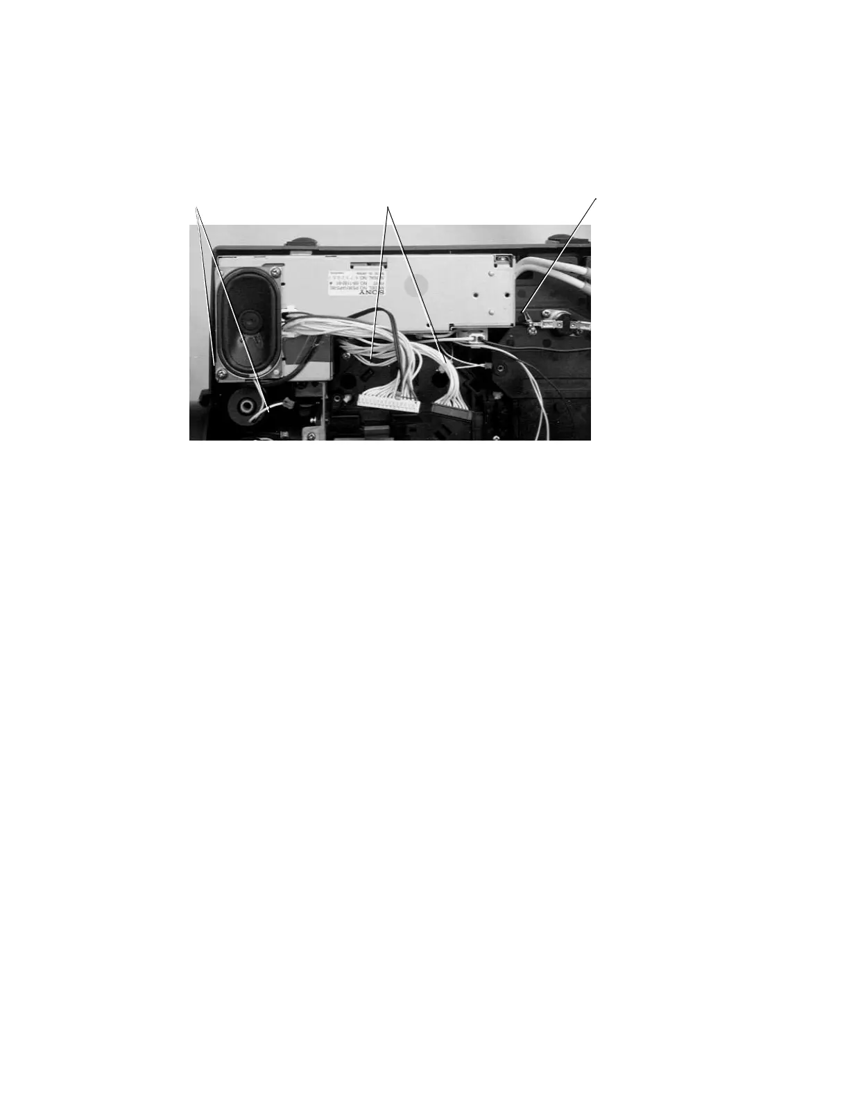
Figure 3-26
6. Remove 5 screws mounting the power supply unit to the lower case.
Screws (4P.C.S.): M3×8 F/ZN Bind: P/N1021824
(mounting torque: 6.0 kg. cm = 5.2 lb. inch)
Screws (1P.C.S.): M3×12 F/ZB Bind: P/N1033692
(mounting torque: 6.0 kg. cm = 5.2 lb. inch)
7. Remove the power supply unit by lifting it straight up.
Caution:
When removing the power supply unit, do not bend or damage the two bosses on the
lower case unit. When installing the power supply unit, align the holes with the bosses. The
intake fan and its peripheral parts are susceptible to dust and dirt. When installing the
power supply unit, check the fan's cleanness and clean it if necessary.
Screw
ScrewsScrews
The screws are
located on the
bottom of the
power supply unit
and are not visible
in the figure.