EPSON PowerLite 5000 Service Manual
4-4
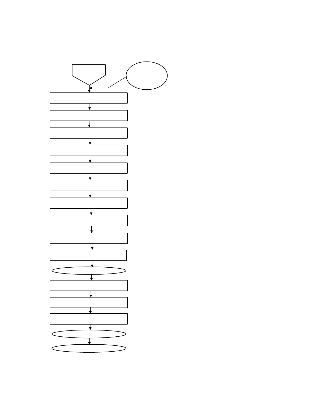
Control Panel
AU Board
Left and Right Speakers
Power Supply Unit
Exhaust Fan
Lamp Thermistor
LV Thermistor
RI Board / FI Board
Driver Board to Main Board
CN Board To Main Board
Disconnect the main Board
FC Board to Driver Board
Intake Fan
Light Valves R/G/B
Attach the main board
Attach the upper case unit
Remove upper
case unit
Note:
Before following this flowchart, turn off the
power and then disconnect the power cable.
• CN600 on the main board (lock type).
• CN300 on the main board to CN101 on the AU board.
• CN603 on the main board to CN100 on the AU board.
• CN601/602 on the main board.
• CN800 on the main board to power supply unit.
• CN860 on the main board to power supply unit.
• Light power cable connector mounting screw.
• CN806 on the main board.
• CN804 on the main board.
• CN803 on the main board.
• CN805 on the main board to CN251 on the driver board.
• CN700 on the main board to CN100 on the driver board.
• CN204 on the CN board / CN203 on the CN board.
• CN802 on the main board.
• CN250 on the driver board.
• CN252 on the driver board.
• CN700/800/900 on the driver board (lock type).
Start
Internal cable connections
Figure 4-3