SC-T7000 series/SC-T5000 series/SC-T3000 series Revision B
DISASSEMBLY & ASSEMBLY Disassembly and Assembly Procedure 182
Confidential
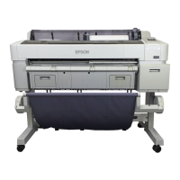
18. Remove the Motor Cover.
19. Disconnect the motor cable from the connector of the Cutter Motor.
Figure 3-144. Releasing the Motor Cable
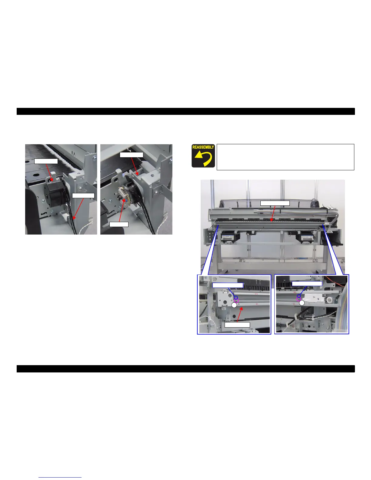
20. Remove the two screws, and remove the CUTTER UNIT.
A) Silver M3x6 screw: 2 pcs
Figure 3-145. Removing the CUTTER UNIT
Motor Cover
Cutter Motor
Motor cable
Connector
Pay attention to the positioning points (See Figure 3-145).
CUTTER UNIT
A
Positioning point
A
Bottom Frame
Positioning pointPositioning point
 Loading...