SC-T7000 series/SC-T5000 series/SC-T3000 series Revision B
DISASSEMBLY & ASSEMBLY Disassembly and Assembly Procedure 113
Confidential
3.4.3.2 MAIN-B BOARD
1. Remove the UPPER LEFT COVER. (p100)
2. Remove the UPPER SUPPORT R COVER. (p94)
3. Remove the PANEL BOARD. (p120)
4. Remove the TOP COVER. (p85)
5. Remove the RIGHT UPPER COVER & RIGHT ROLL COVER. (p95)
6. Remove the REAR RIGHT LOWER COVER. (p99)
7. Remove the PSH BOARD. (p118)
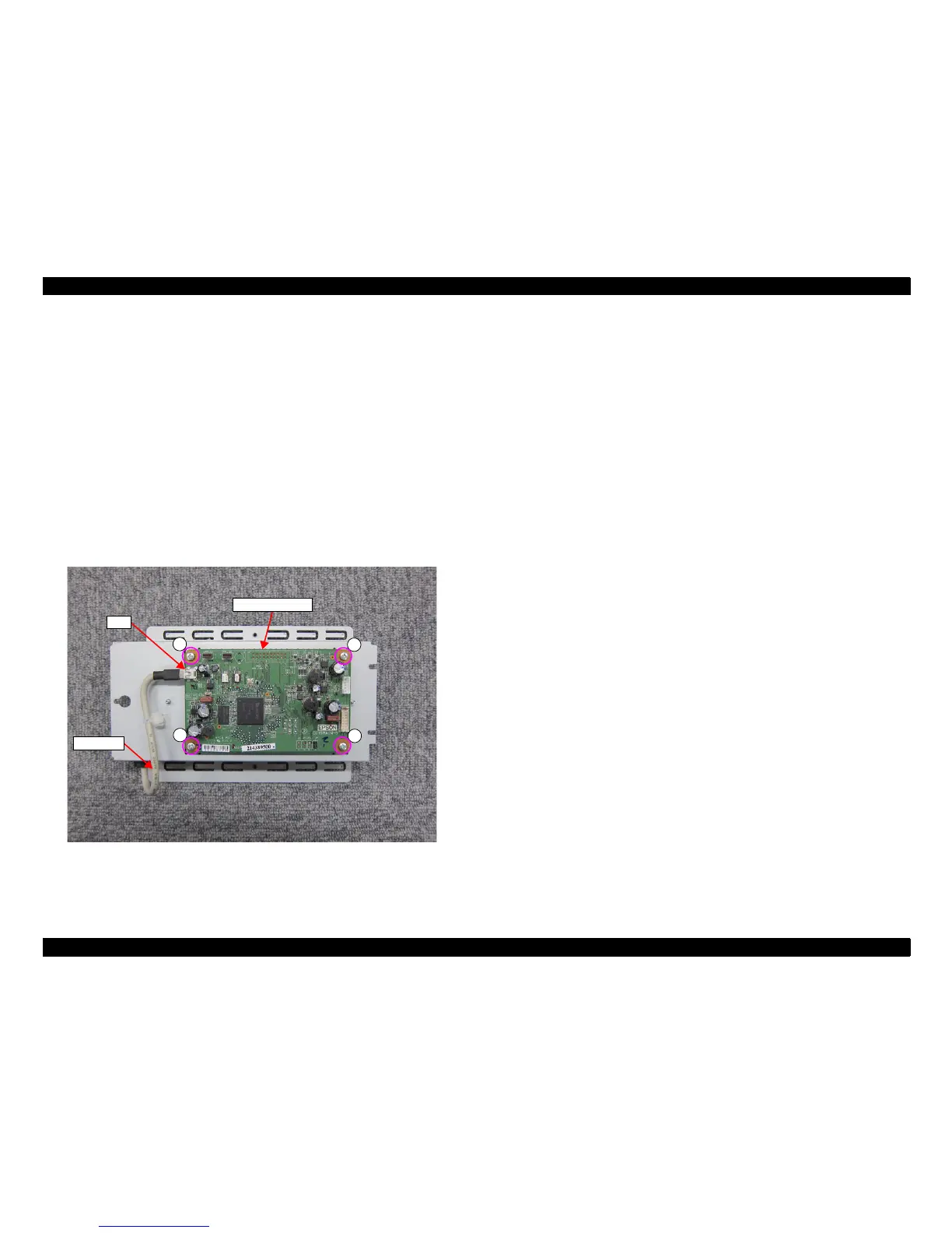
8. Disconnect the USB Cable from the connector (CN6) of the MAIN-B BOARD.
9. Remove the four screws, and remove the MAIN-B BOARD.
A) Silver M3x6 screw: 4 pcs
Figure 3-42. Removing the MAIN-B BOARD
MAIN-B BOARD
A
A
A
A
CN6
USB Cable
 Loading...