SC-T7000 series/SC-T5000 series/SC-T3000 series Revision B
DISASSEMBLY & ASSEMBLY Disassembly and Assembly Procedure 84
Confidential
Manual
1. Remove the UPPER LEFT COVER. (p100)
2. Remove the UPPER SUPPORT R COVER. (p94)
3. Remove the PANEL BOARD. (p120)
4. Remove the TOP COVER. (p85)
5. Remove the RIGHT UPPER COVER & RIGHT ROLL COVER. (p95)
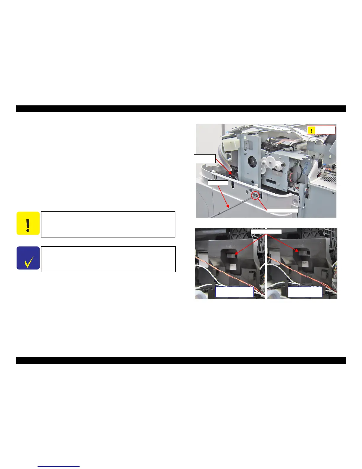
6. Insert a screwdriver into the cover through the hole as shown in the figure.
7. While viewing the CR Lock Lever status from the front of the printer, turn the
white shaft of the Pump Cap Unit counterclockwise with the driver.
8. The CR Lock Lever is lowered. Check that the lever reaches the CR unlock
position, and stop turning the white shaft.
Figure 3-9. Unlocking the CR Unit
Figure 3-10. Status of the CR Lock Lever
C A U T I O N
Do not turn the white shaft clockwise with the driver.
C H E C K
P O I N T
When the CR is unlocked, it clicks.
Use a screwdriver with a 170 mm or longer shaft.
Insert driver here
Screwdrive
PUMP CAP
UNIT
C A U T I O N
No clock
rotation!
CR Lock Lever
CR unlocked
(The Lever is lowered)
CR locked
(The lever is raised)
 Loading...