5. Lift from underneath both ends of the lamp assembly (lamp, cable, and lamp support)
to remove it. The lamp assembly snaps in and out.
6. Turn over the scanner mechanism so you can see the circuit boards. Pull the lamp
cables out of the two black hooks and remove the lamp connector. Then pull out the
cable and connector.
4.2.4.3 Removing the Document-End sensor - not an ASP!?!?
1. Remove the scanner as described in “Removing the Scanner Mechanism” on page99.
2. Open the scanner cover and remove two screws (CBP 3x6).
3. Using a flat-tip screwdriver or similar tool, push out the sides of scanner cover’s sides
so the cover comes free from the notches.
4. Remove three silver screws (CBP with flange 3x6) plus the grounding plate, one screw
(CBP with flange 3x6), and two black screws (CBP 3x6) securing the Document End
sensor.
5. Remove the sensor.
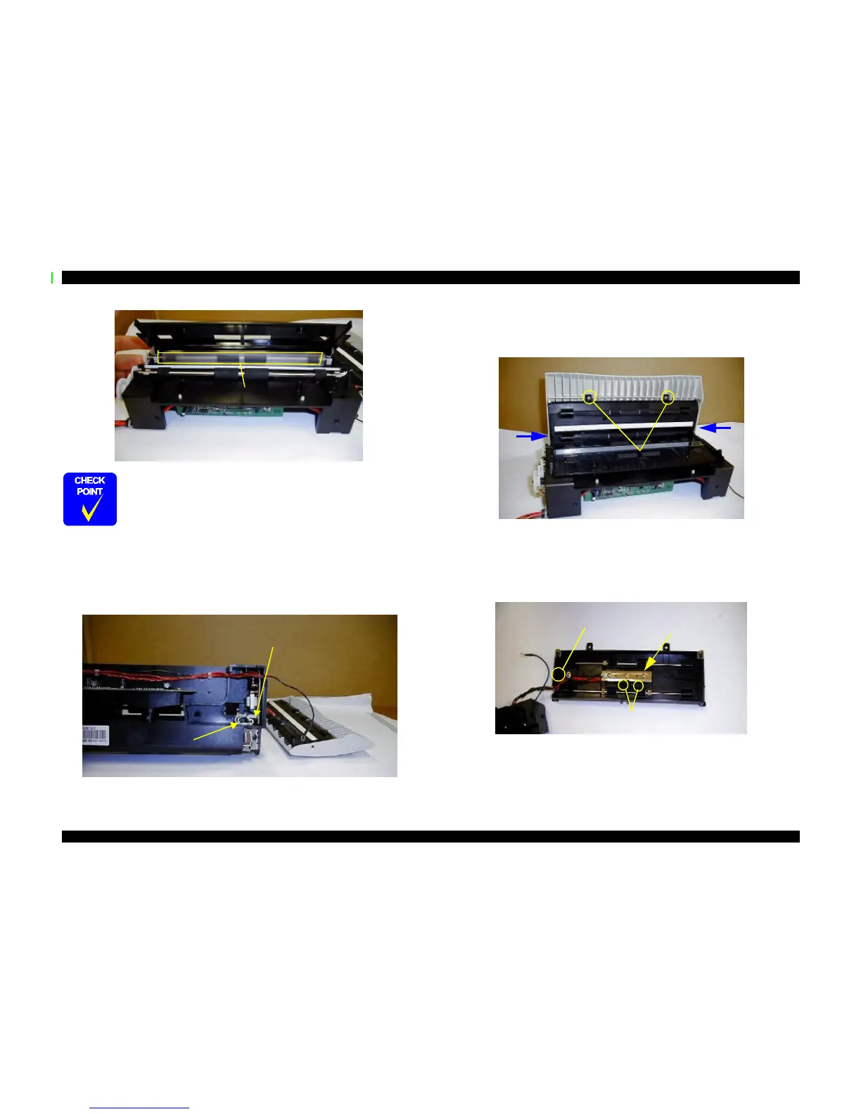
When reinstalling the document guide, make sure the protective film
slides under the forward rollers.
Protective film
Two black hooks
Lamp connector
Notches on sides
of cover
Two screws
Two screws
Remove one screw
Remove three screws
and grounding plate.
 Loading...