Drive from the PF motor is sent to the PF rollers and paper eject rollers as described
below.
o To the PF rollers:
PF motor pinion gear (CCW rotation)→ Gear 73.6 → PF rollers
o To the eject rollers:
PF motor pinion gear (CCW rotation)→ Gear 73.6 → Combination gear (13.5,
308) → Spur gear (28) → Paper eject rollers
NOTE: Above CCW rotation is mentioned viewing from the PF motor pinion gear side.
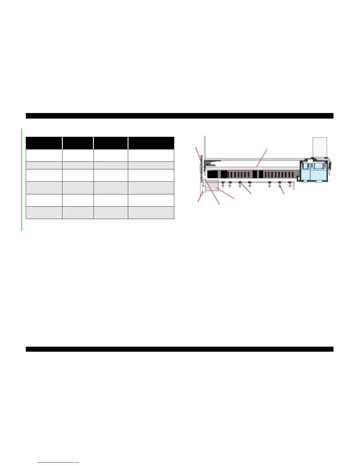
Figure 2-8 shows a paper feeding mechanism block diagram, which includes the parts
along the PF motor drive-transmission paths.
Figure 2-8. Paper Feeding Mechanism (Top View)
The printer feeds paper from the ASF (when the PE sensor located near the carriage
motor detects paper is loaded) through the paper path and stops feeding when the
paper’s leading edge reaches the halfway point of the front paper guide. To correct for
any misfeeding, the paper is fed back toward the ASF a predetermined number of steps
and then it is fed forward again until it reaches the top-of-form position.
Once the printer starts printing, it advances paper using the PF rollers and subrollers
until it reaches the last 14mm of the paper, when it advances the paper using the star
wheel gear and paper eject rollers.
Torque sent from the ASF/Pump motor to the ASF unit via the disengage mechanism is
used for the following operation.
Table 2-7. Motor Control at Each Mode
Printing mode
Drive Speed
[CPS]
Drive frequency
[PPS]
Drive method
High Speed Skip 340 4080
Double 1-2, 2-2,1-2 phase
drive*
Normal Printing 200 2400 Double 1-2, 2-2 phase drive
Capping 80 960
2-Double 1-2, 2-2 phase
drive
Wiping 40 480
2-Double1-2, 2-2 phase
drive
Cap (Valve Release) 20 240
4-Double1-2, 2-2 phase
drive
Withdrawal of cap 5 60
4-Double 1-2, 2-2 phase
drive
PF motor
Paper Eject Roller
PF Roller
Star Wheel Assy.
Combination
Gear13.5,30.8
Gear 28
Gear
73.6
 Loading...