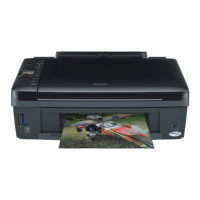
n To the scanner: CN14, CN11, CN12, CN13
To the control panel: CN2
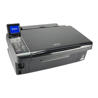
n To the printer: CN4, CN5, CN6, CN7, CN8, CN9
5. After removing all of the cables, detach the circuit board tray completely from the
printer mechanism.
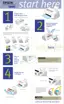
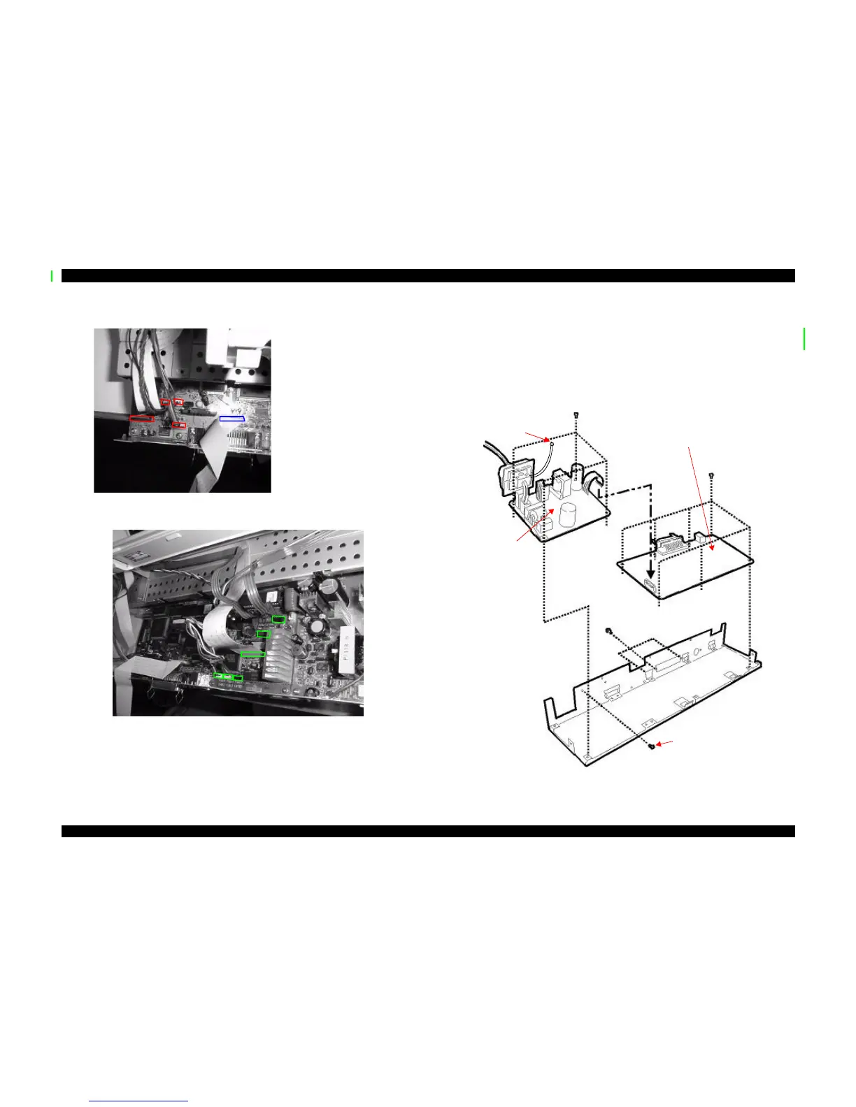
4.2.3.1 Removing the B101 MAIN Board
Follow the steps in the previous section to remove the circuit board tray from the Stylus
Scan. To remove the B101 MAIN Board from the tray, remove:
n The cable (CN10) that connects to the power supply board
n Seven (CBS 3x6) screws securing the board
n Three (CBS 3x6) screws securing the interface connectors
Figure 4-5. Removal of the circuit boards
Red = Scanner
Blue = Control Panel
Ground Screw for
ground connector
MAIN Board
Power Supply
Board
Ground
connector
 Loading...