5 • Description of the Controls
42 / 106
80113-101_V25087
2023-11
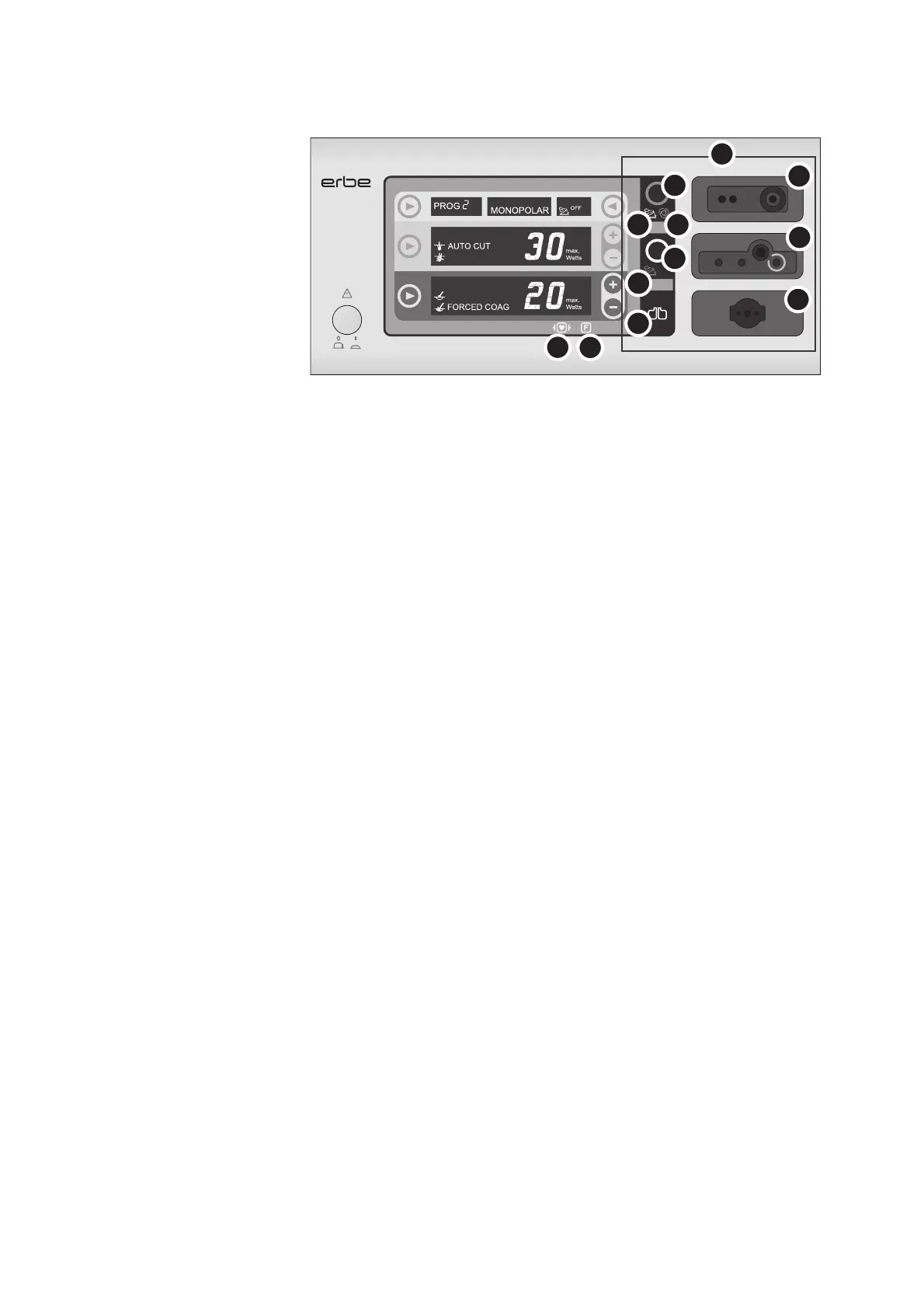
Fig. 5-2
(8) Socket area
(8a) Neutral electrode indicator light
Display green: The monopolar socket can be activated.
Display red: The monopolar socket cannot be activated.
(8b) Footswitch indicator light
If the connected footswitch is assigned to a socket, the corresponding footswitch in-
dicator light illuminates.
(8c) Focus button
"Brings into focus" (selects) an instrument socket: The current settings of the socket
in focus are displayed.
The socket currently in focus can be identified by the illuminated Focus button.
The button is yellow while the CUT current is activated; the button is blue while the
COAG current is activated.
(8d) AUTO START indicator light
The AUTO START indicator light illuminates if the AUTO START function is assigned to
the bipolar socket (available for the VIO
100 C only).
(8e) Bipolar socket
Socket for connecting a bipolar instrument.
(8f) Monopolar socket
Socket for connecting a monopolar instrument.
(8g) Neutral electrode socket
Socket for connecting a neutral electrode.
(9) Symbol "Protection from
leakage currents"
The patient circuit is insulated against ground. The risk of leakage currents and thus
the risk of burns is greatly reduced for the patient.
(10) Symbol "Defibrillation-proof
type CF applied part"
All HF sockets and the neutral electrode socket (applied parts) meet Type CF require-
ments and are protected against the effects of defibrillator discharge.
8c
8c
8b
8b
8d
8a
8f
8g
8e
9
10
8
VIO 100 C