CP-2232E
Remote Control Panel
Revision 1.1 Page 3
D
1 D
2
L1
L2 L
3
L
4
L
5
L6
L7
L
8
L9
L
10
L
11 L
12
L13
L14
L
15 L
16
L
17 L
18
L19
L20
L
21 L
22 L
23
L24
L
25
L
26
L27
L
28 L
29 L
30
L31
L
32
S1
S
2
S3
S4
S
5 S
6 S
7
S8
U
1
U
2
U3
U
4
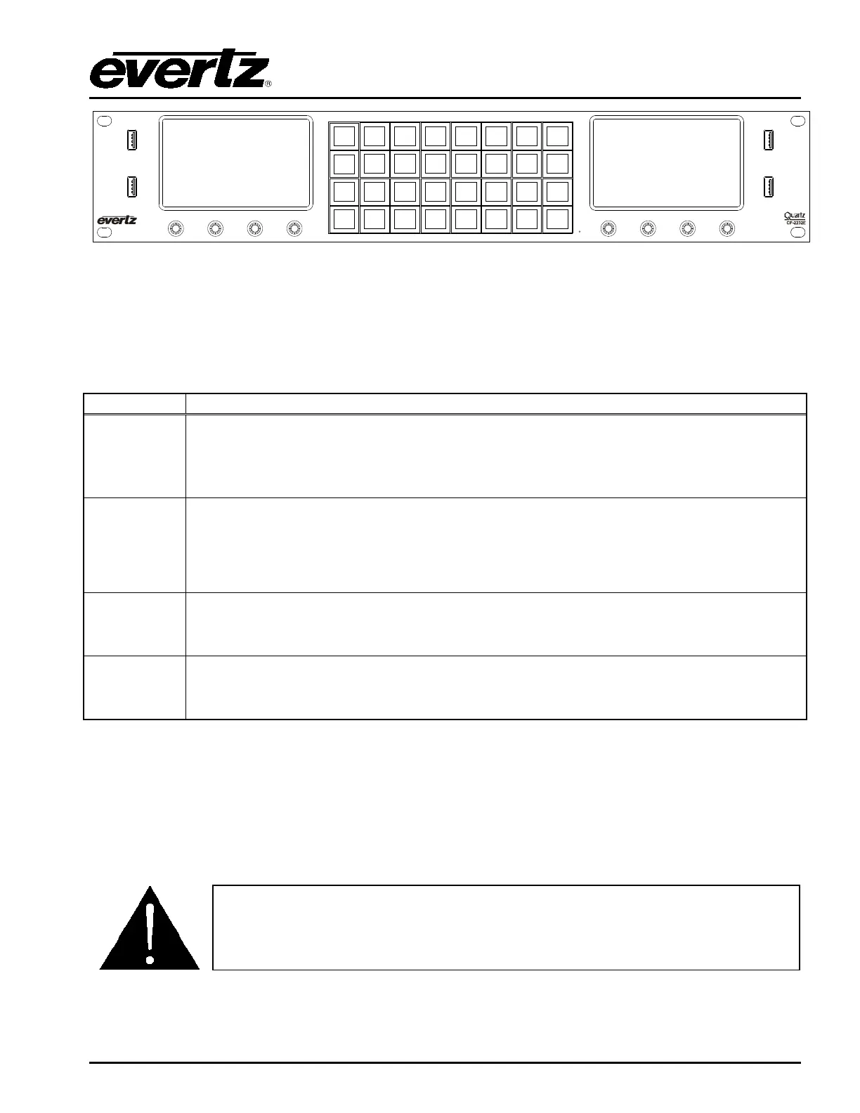
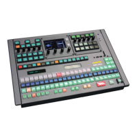
Figure 2-2: CP-2232E Front Control Panel
Please note that the labels in Figure 2-2 will NOT be displayed on the front panel of your CP-2232E
device. The labels listed above are for reference purposes only when describing the panel controls in
the following sections of the manual. The following chart describes the label and function of the
associated button.
D1 & D2
These labels identify the two display screens on the CP-2232E front panel. When
operating the panel, the content will be displayed on these screens.
L1 to L32
There are thirty-two LCD buttons located on the front panel, which are labelled L1 to
L32 in Figure 2-2.
S1 to S8
S1 to S8 identifies the eight shaft encoders that are available on the front panel. The
user can adjust parameters or toggle through items by turning the shaft encoder knobs
left and right. The user can also select items by pressing in the shaft encoder.
U1 to U4
There are four USB ports located on the front panel, which are labelled U1 to U4 in
Figure 2-2. These ports are used for USB-based mouse and/or keyboard connections,
and local upgrading of the panel.
2.3. POWER CONNECTIONS
The CP-2232E comes with an auto-ranging DC voltage adapter that automatically senses the input
voltage. Power should be applied by connecting a 3-wire grounding type power supply cord to the
power entry module on the DC voltage adapter. The power cord should be minimum 18 AWG wire
size; type SVT marked VW-1, maximum 2.5 m in length. The DC cable of the voltage adapter should
be connected to the DC power jack on the rear of the panel.
CAUTION: TO REDUCE THE RISK OF ELECTRIC SHOCK, GROUNDING OF
THE GROUND PIN OF THE MAINS PLUG MUST BE MAINTAINED.