Getting Started with Your Unit
FTB-2/FTB-2 Pro and FTB-4 Pro 47
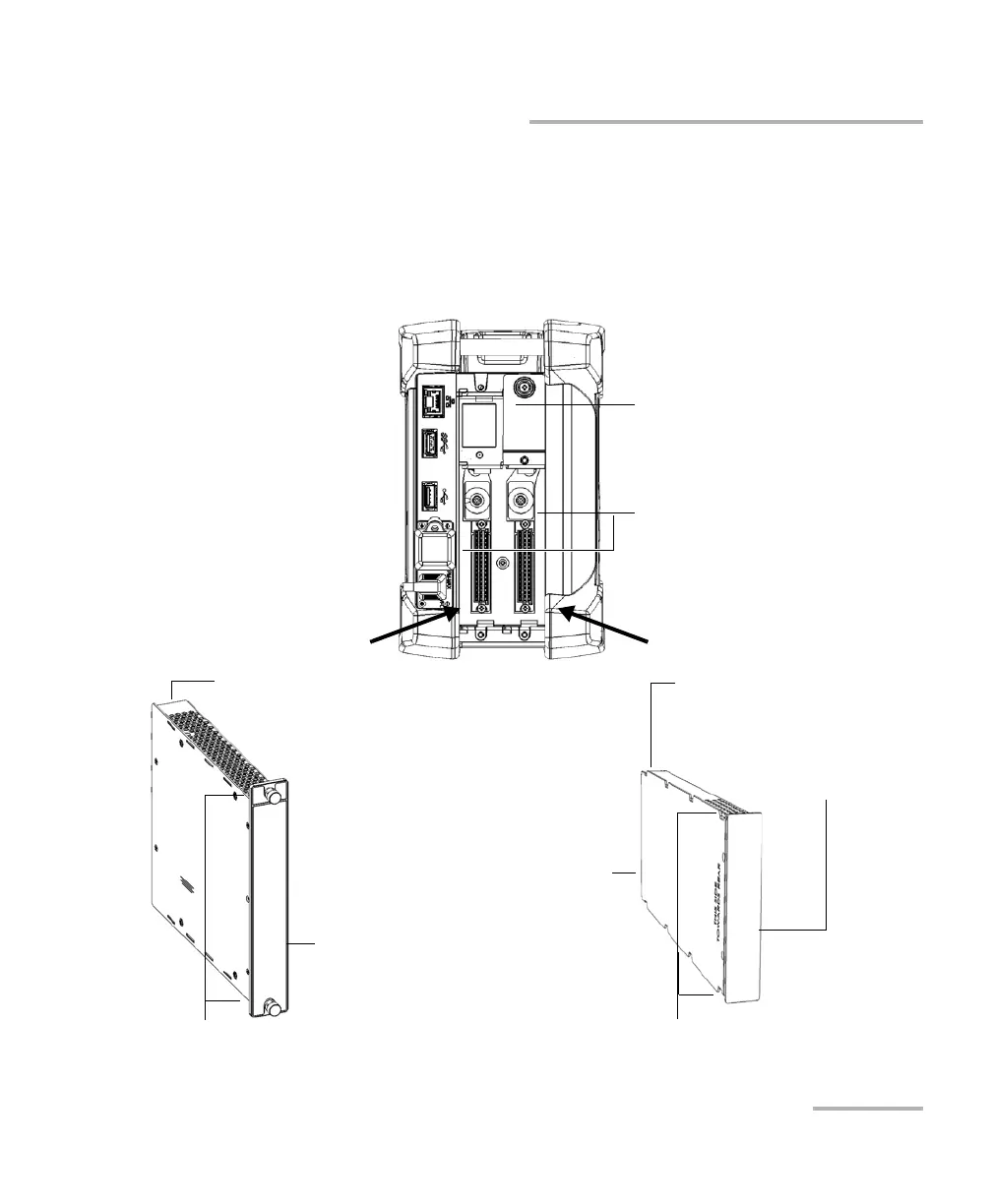
Inserting and Removing Test Modules
3. Take the module and place it so that the connector pins are at the
back, as explained and shown below.
The identification sticker must be on the right side and the protruding
edges on the left side. In the case of the FTB modules, ensure that the
retaining screw hole is over the connector pins.
Right panel
FTB module
Protruding edges on left side
Identification sticker
on right side
Connector pins at the back
FTBx module
Adapter
for FTB modules
Protruding edges on left side
Identification sticker
on right side
Connector pins
at the back
Retaining screw hole at the back
Slots
for FTB and FTBx modules
ООО "Техэнком" Контрольно-измерительные приборы и оборудование www.tehencom.com