32
SunSDR2 DX User Manual
© 2020 Expert Electronics
ExpertSDR2 SOFTWARE DESCRIPTION
Capture (before modulator or after modulator) – select where you want to capture TX signal,
before or after modulator.
This function is synced with the Low latency check-box in Options-> Device menu-> TX tab->
Monitoring in PC.
Accumulate – add a line showing peak values during the time of analysis.
Pink noise line (Enable) – enable the pink line showing the energy spread by frequency.
Level – pink noise line level.
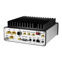
It consists of the following functions:
DC block's purpose is to effectively remove Time
constant in the microphone signal. Changing of Time constant influence quality of the applied
filter. You can test it by increasing or decreasing Time constant value in 1-10 ms range, you’ll
notice low frequencies reduction with 1 ms value and amplifying with 10 ms value.
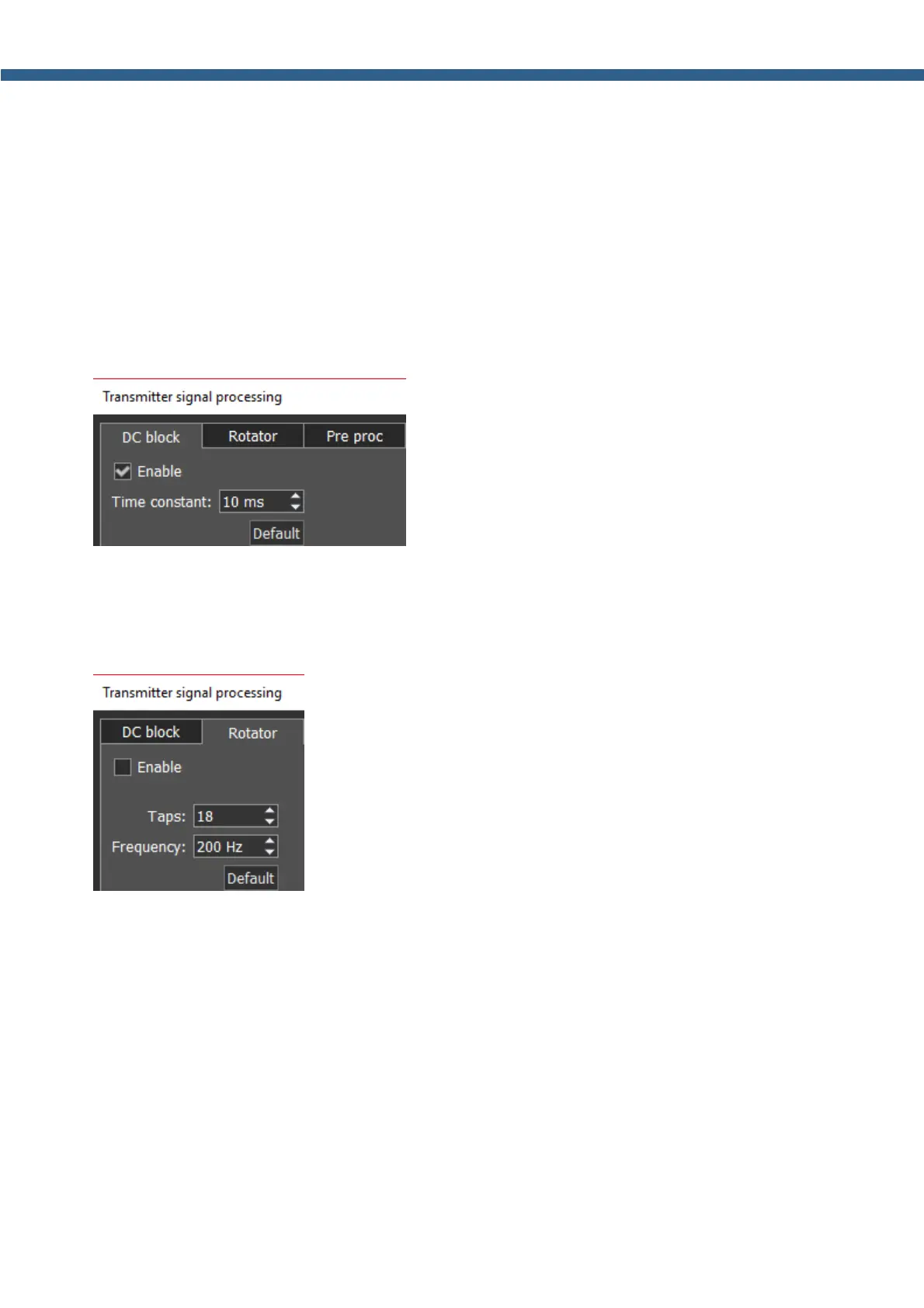
Phase Rotator.
Taps – amount of phase rotators (stages).
Frequency – frequencies below will change the phase.
The algorithm itself is fairly simple, firstly you should reach the max symmetric characteristic by
adjusting the Taps parameter (in some applications it's called stages), after each change of the
parameter check the result in the analyzer. Then change the Frequency parameter, with a 50
Hz step. Frequencies lower than the Frequency value are not rotated, everything above are
processed by the Rotator. All voices are unique and have their own AFC, that's why this module
should be adjusted by the user himself.
Setting the right rotator settings is easy, you are trying to reach max symmetry with the Taps
parameter (in some applications it is called stages), after each change of this parameter check
the result on the analyzer.