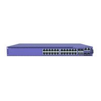
The 5420 Series includes the following models:
• 5420F-8W-16P-4XE Switch Features on page 16
• 5420F-24P-4XE Switch Features on page 17
• 5420F-24S-4XE Switch Features on page 18
• 5420F-24T-4XE Switch Features on page 19
• 5420F-16MW-32P-4XE Switch Features on page 20
• 5420F-16W-32P-4XE Switch Features on page 21
• 5420F-48P-4XE Switch Features on page 23
• 5420F-48P-4XL Switch Features on page 24
• 5420F-48T-4XE Switch Features on page 25
• 5420M-24T-4YE Switch Features on page 26
• 5420M-24W-4YE Switch Features on page 27
• 5420M-16MW-32P-4YE Switch Features on page 28
• 5420M-48T-4YE Switch Features on page 30
• 5420M-48W-4YE Switch Features on page 31
Management
An RJ45 serial console port on the front panel of the 5420 Series switch enables you
to connect a terminal and perform local management. An Ethernet management
port can be used to connect the system to an out-of-band management network
for administration. Alternatively, you can use an Ethernet cable to connect this port
directly to a laptop to view and locally manage the switch conguration. The Ethernet
management port supports 10/100/1000 Mbps speeds.
There is one Micro-B USB console port on the front panel. If the Micro-B USB console
port is connected, it will be selected over the RJ45 console port. The Micro-B USB
console port will disconnect when the switch is rebooted. You can re-connect the port
if needed. When the Micro-B USB console is active, any messages from the switch to
the client terminal will be echoed to both the USB console and the rear panel RJ45
serial port; however, no user input will be accepted from the rear panel port.
Tip
Using a Micro-USB Type B to USB Type A cable, connect the Micro-USB Type B
end to the switch, and the USB Type A end to a laptop or PC and complete the
driver installation steps.
ExtremeSwitching 5420 Series Overview Management
ExtremeSwitching 5420 Series Hardware Installation Guide 13

 Loading...


