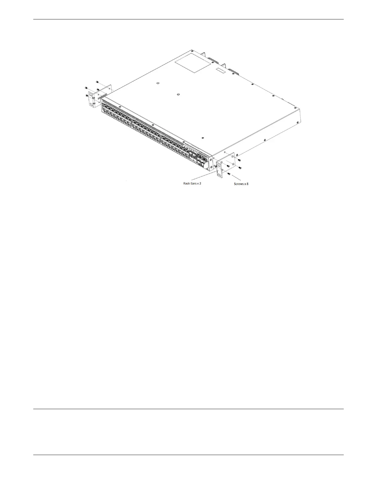
Figure 44: Front Mount: Attaching Short Mounting Brackets
2. Use the small bracket-mounting screws (provided) to secure the bracket to the
switch housing.
If using screws other than those provided, ensure that the threaded length of the
screws is within 4 to 5 cm.
3. Repeat step 1 and step 2 to attach the other bracket to the other side of the switch.
4. Secure the mounting bracket anges to the rack, using screws that are appropriate
for the rack.
(Rack-mounting screws are not provided.)
5. If a grounding lug is present, ground the switch.
a. At one end of the wire, strip the insulation to expose 1/2 inch (12 mm) of bare wire.
b. Identify the grounding lug on the back of the switch.
c. Insert the stripped wire into the grounding lug.
d. Tighten the retaining screw with a straight-tip torque screwdriver to 20 in-lb (2.25
N m).
e. Connect the other end of the wire to a known reliable earth ground point at your
site.
After the switch is secured to the rack or cabinet, install optional components using the
instructions in Install Optional Components on page 76.
Then, install one or two power supplies using the instructions in Install Internal AC
Power Supplies on page 77.
Install Optional Components
After the switch is secured to the rack, install optional components.
ExtremeSwitching switches support the use of pluggable transceivers and cables in the
SFP+, SFP28, QSFP+, and QSFP28 formats.
Install Optional Components Installing Your Switch
76 ExtremeSwitching 5420 Series Hardware Installation Guide
 Loading...

