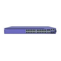
Table 20: Port LEDs in SYS Mode (default) (continued)
Color/State Meaning
Slow blinking amber No link, or disabled port; port is powered
Alternating amber and green Port has a power fault
Off Port is not powered, has no link, or is disabled
Port LEDs in SPD Mode
The port LEDs enter the SPD display mode when the Mode button is pressed one time,
indicated by the SPD LED. SPD mode is used to help determine the operational speed
of a port.
There are two LEDs per SFP-DD port on 5420 models. When an SFP-DD port is used
for Ethernet and stacking is disabled, each SFP-DD port can be used as either a single
SFP+ port or two SFP+ ports if an SFP-DD transceiver is used on 5420M models. When
the SFP-DD port is used for as a single SFP+ port, the rst LED represents link and
trafc, while the second LED is not operational. When the SFP-dd port is used as two
SFP+ ports, the rst LED represents link and trafc for the rst port, and the second
LED represents link and trafc for the second port. 5420F models are limited to one
10Gbps port per SFP-DD port in Ethernet mode with stacking disabled. The second
SFP+ port is not available and the second LED is not operational.
In stack mode, each SFP-DD port can be used as one 20Gbps SFP+ port, or one 10Gbps
SFP+ port, depending on the stack speed and optic used. The rst LED represents the
link state and trafc of the stack port with solid or blinking green. The second SFP+ port
is not available and the second LED is not operational.
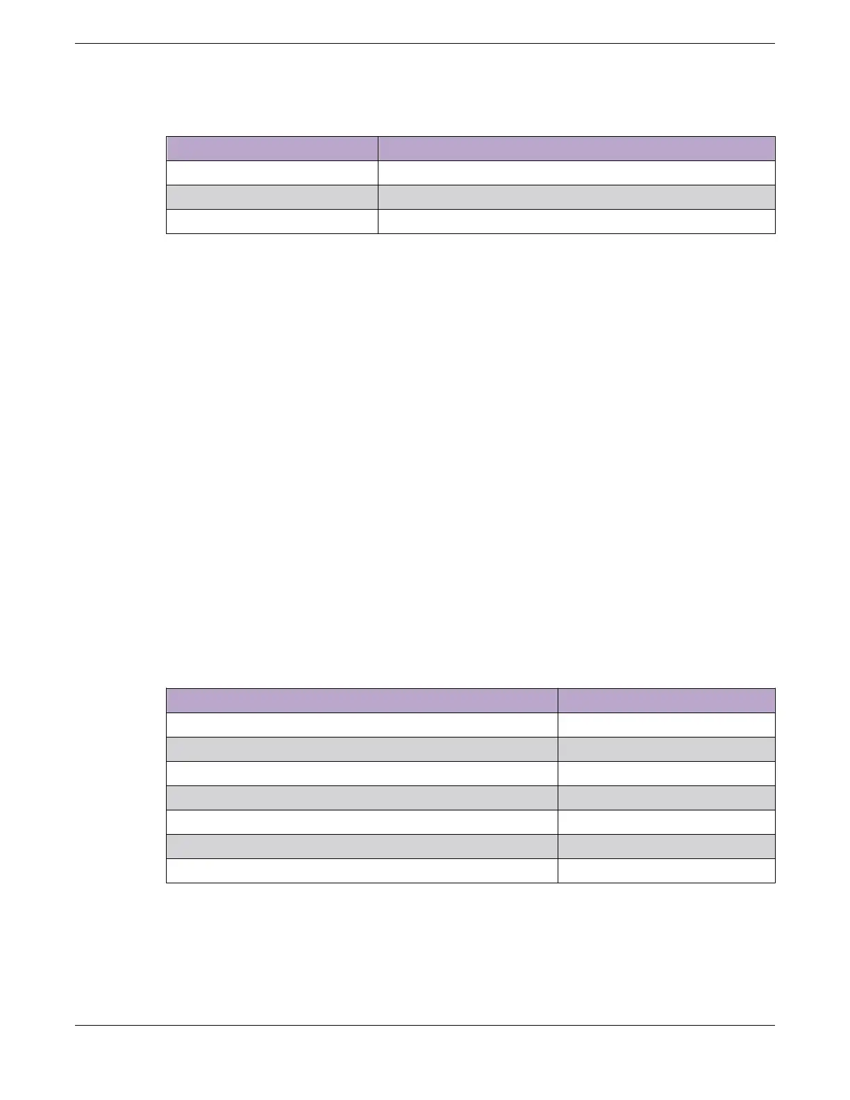
Color and blink pattern indicate speeds, as referenced by the following table:
Table 21: Port LEDs in SPD Mode
Color/State Speed
Steady green 10Mbps
Blinking green 100Mbps
Solid amber 1000Mbps
Slow blinking amber 2.5Gbps
Slow blinking green 10Gbps
Fast blinking green 25Gbps
Fast blinking green 40/50Gbps
Monitoring the Device Port LEDs in SPD Mode
ExtremeSwitching 5420 Series Hardware Installation Guide 93
 Loading...

