Port LEDs in STK Mode
The port LEDs enter the STK display mode after the Mode button is pressed twice,
indicated by the STK LED. STK mode is used to indicate slot presence and slot number
via the rst eight port LED, as referenced by the following table:
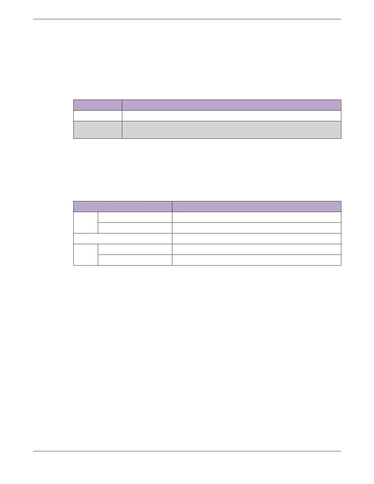
Table 22: Port LEDs in STK Mode
Color/State Speed
Steady green The slot corresponding to the port number of the LED is present.
Blinking green This slot has a slot number corresponding to the port number of the
blinking LED.
Management Port LEDs
The management port uses two LEDs to indicate port activity and link status, as
referenced by the following table:
Table 23: Management Port LEDs
Right side LED State
Link Solid Green Link up
Off No link up or port disabled
Left side LED State
Act Blinking Green Packet transmitting or receiving
Off No packet transmitting or receiving
Port LEDs in STK Mode Monitoring the Device
94 ExtremeSwitching 5420 Series Hardware Installation Guide
 Loading...

